Then that capacitor is in the audio signal path as well as any series cap, isnt it?
You circuit is how you would simulate it and the practical circuit will have a few more parts to it.
I always drive SITs with a transformer and the circuit from Zen Mod captures almost precisely how I do it as well, including the value of the DC resistance. Your SIT requires some examination, I believe, before you could finalize your own circuit. If I were in your shoes, I would mount the SIT on a heatsink, connect them to lab power supplies and measure things you need to know to design the circuit. Again, the key one is the leakage current, in my opinion. And then heat it up externally and measure. Heat it by power produced by transistor itself and measure. And then take a different transistor and measure it again...
It happened to be the beginning of the pandemic for my PP project, so I was stuck at home anyway and I used this time to do a lot of measurements. I had app 40 devices at that time, so it took me a few weeks before I understood how it should look.
And then the amplifier was built and it was working great and then my stupidity pushed my hand where it should not have been. And I lost my best pair of SITs. After I replaced it, I started blowing a fuse on B+ after 10-20 minutes of operation and that brought me back to measurements and I found that the dynamics of thermally induced gate leakage current increase has much wider spread than I originally thought. Some keep climbing steadily, some got a hockey stick increase at some temperature.
SITs are absolutely great for sound but they are like people - every one is somehow different even if it looks the same...
Member
Joined 2009
Paid Member

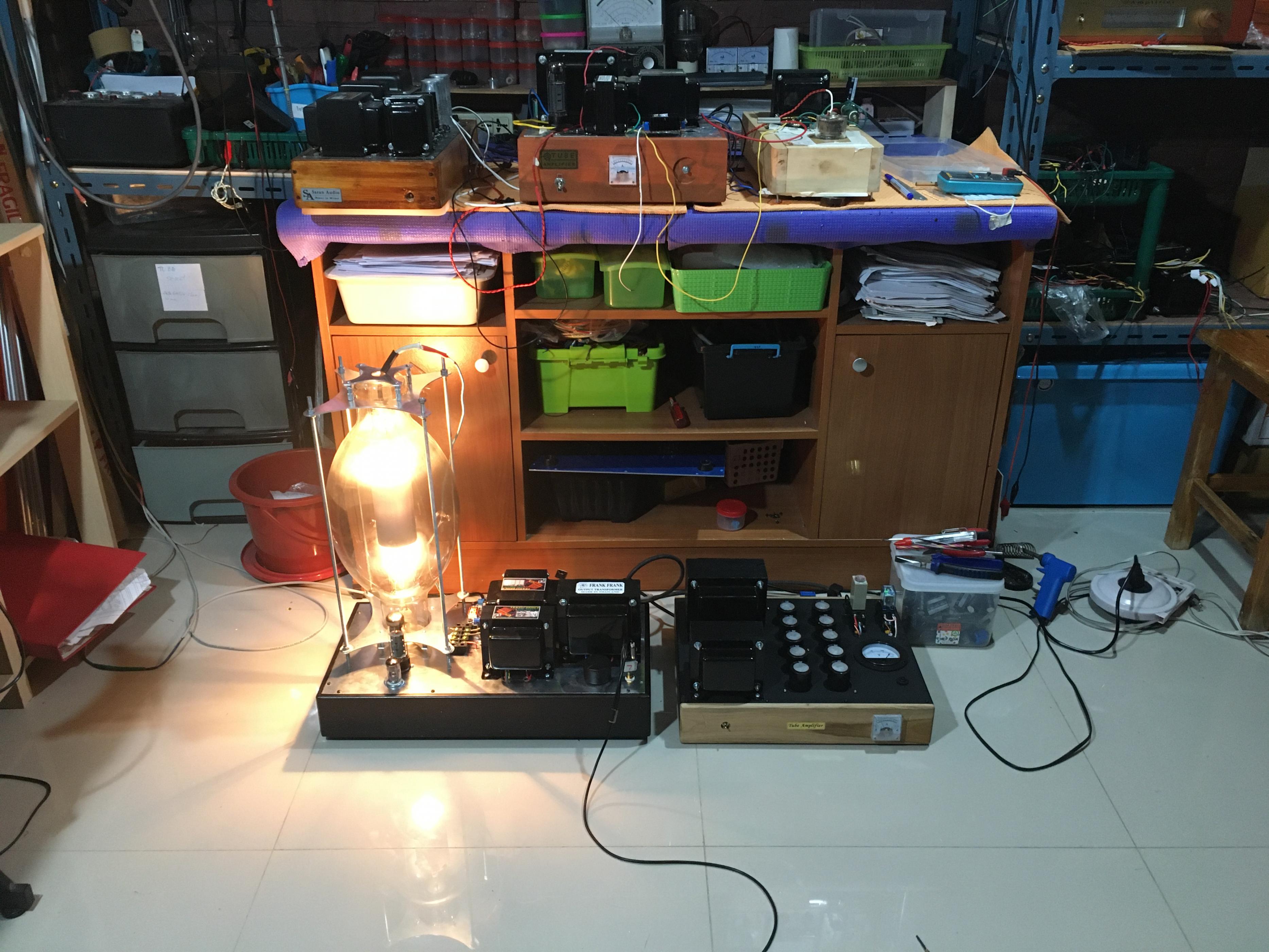
Already done, on other threads. We use Korg Nutube with B1, 6SN7 in SY's Impasse with F4, giant 300W light bulbs in DeLite, Pascal Nguyen IV-8 VFD B1 and many more, great sound with satisfying warm glow of vacuum state stuff. 😀... that actually glow!?
Ain't that the truth. Perhaps we should prototype a cute little GM100 preamp to rectify the problem. As Papa sez, ........ while they last. 
I can not think of anything more proper than a pair of air core transformers to complement the linearity of those cute triodes. Pity Magura has not been posting here for a bit. 
Magura is making money, no time for fun
🙂
you nutz, air core for GM70/100
why not for VT4C ......... it would be weight and size of small car
🙂
you nutz, air core for GM70/100
why not for VT4C ......... it would be weight and size of small car
While not as manly as the size of amps Ken English used to care for, the point of the idea it to make it rather difficult for you to use the word sissy. 😀


cute little GM100
You can not scare us SIT people with GM100! Could GM100 deliver 7W into 8Ohm from DAC output with 2% distortions in a circuit like that?
Attachments

Last edited:
I am one of SIT people too. No SIT people should be scared of the GM100, we love them cute triodes instead.
About your question on the distortion, I can not say from experience, need to complete the prototype first, which will not be soon due to my budgetary condition. However, looking at the datasheets, I'm pretty sure it can deliver 2% @7W into 8 ohm when setup as output stage appropriately in a schematic similar to he one you posted. But it would probably be easier to setup 2% @ 100W and 10% @ 200W into 8 ohm, and not directly from DAC output. As a preamp it has a mu of ~18, enough to drive F4 full tilt from DAC output at miniscule ppm THD.
From My Gm100 se mono block thread.
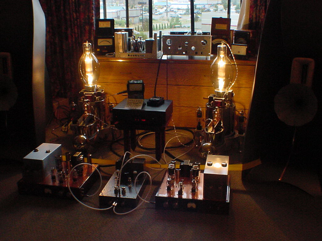
Ain't they cute? I'd encourage SIT guys to use them, probably as preamp (or simpler as audio gear lighting or room decoration) to rectify the issue of our gears being called sissy. I know ZM loves them so much he'll have a hard time calling them sissies. And remember what Papa said .... while they last. 😀
About your question on the distortion, I can not say from experience, need to complete the prototype first, which will not be soon due to my budgetary condition. However, looking at the datasheets, I'm pretty sure it can deliver 2% @7W into 8 ohm when setup as output stage appropriately in a schematic similar to he one you posted. But it would probably be easier to setup 2% @ 100W and 10% @ 200W into 8 ohm, and not directly from DAC output. As a preamp it has a mu of ~18, enough to drive F4 full tilt from DAC output at miniscule ppm THD.
From My Gm100 se mono block thread.
Ain't they cute? I'd encourage SIT guys to use them, probably as preamp (or simpler as audio gear lighting or room decoration) to rectify the issue of our gears being called sissy. I know ZM loves them so much he'll have a hard time calling them sissies. And remember what Papa said .... while they last. 😀

Writing the response longer than usual - being constantly interrupted by me bowing every time I look at your pictures... 🙂
I would looove to have budget constraints like yours!
I would looove to have budget constraints like yours!
But still, 7W in a single stage?...
It is actually less than 7W into the load - the output impedance is at app. 2 Ohm.
It is actually less than 7W into the load - the output impedance is at app. 2 Ohm.
Ehhhm Radiola, those are not mine, I borrowed the pics from the GM100 thread I linked on my prev post. 🙂
Them GM100 are 1000W triodes, almost 200W achievable with adequate input drive.
Them GM100 are 1000W triodes, almost 200W achievable with adequate input drive.
Last edited:
same as big speakers, these big amps are just compensation

all my speakers and all my amps are size of Zippo lighter
all my speakers and all my amps are size of Zippo lighter
Member
Joined 2009
Paid Member
I am one of SIT people too. No SIT people should be scared of the GM100, we love them cute triodes instead.
now those are real triodes!
whereas these SITs, I don’t know, ‘sit’ is something you tell your dog to do.
I’m going to have to listen to one of these SITs again, it's been awhile.
- Home
- Amplifiers
- Pass Labs
- Look, Ma, No Coupling Caps! A Transformer Coupled VFET/SIT Amp Design