Hi,
Yup, constant group delay seems O.K to me.
The plot also shows the obvious presence of a well implemented filter...
Although I'd rather live in an environment where I wouldn't need one...and I think I do...🙂
Chiwawa, 😉
If you'll look at the group delay plot, you'll see that it's flat out to 1 MHz (excepting the low frequency group delay due to the high pass element). Meaning that all frequencies are arriving when they're supposed to and there's no alteration of the waveform.
Yup, constant group delay seems O.K to me.
The plot also shows the obvious presence of a well implemented filter...
Although I'd rather live in an environment where I wouldn't need one...and I think I do...🙂
Chiwawa, 😉
fdegrove said:Yup, constant group delay seems O.K to me.
The plot also shows the obvious presence of a well implemented filter...
Although I'd rather live in an environment where I wouldn't need one...and I think I do...🙂
Yes, but we should not forget that there are some poor souls out there not as fortunate as we. There but for the grace of God and all that. 🙂
se
janneman said:Hi all,
I am working on a kind of universal channel amplifier. One of the issues is local power regulation for each active element. I thought about using an opamp with a reference voltage at its input and the output serving as the local supply voltage. Kind of like a super regulator without the output transistor. Performance would be somewhere between a super regulator and a standard 3-terminal regulator, for a low price, especially using dual opamps.
My two cents says, just follow standard 'good' op-amp layout practices, and bypass the amp with a small eletrolytic, and some ceramic or other high frequency caps. Then test the thing. Transitent testing can tell you a lot about how well it's performing.
I've used an LM833 in a bench regulator that I built, and it worked out very well (with a pass transistor). Performance was much better than any 3 terminal regulator I had in the shop at the time. Very Very dissapointed with the 3 terms...
-Dan
reality check please, waiter!
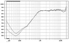
And the buzzwords for today are " Group Delay" brought to you by our resident buzzword enthusiast. Anybody what to speculate on the phase shift and group delay of this highly regarded dome tweeter with a 6 dB peak at 20 kHz. I thought not...... I am sure you are all listening to tweeters flat and minimum phase to 100 kHz on your minimum phase recordings. I think you guys need to get out in the real world once in a while. I bet none of you could hear a second order filter at 50 kHz built with very good parts. I sure as sure as hell don't claim I can. put in a 1st order at 100 kHz with ceramic or silver mica (most of the ones I've tried) and I bet it would be different story. I think some of you are lot more "High" than "Fi".......
And the buzzwords for today are " Group Delay" brought to you by our resident buzzword enthusiast. Anybody what to speculate on the phase shift and group delay of this highly regarded dome tweeter with a 6 dB peak at 20 kHz. I thought not...... I am sure you are all listening to tweeters flat and minimum phase to 100 kHz on your minimum phase recordings. I think you guys need to get out in the real world once in a while. I bet none of you could hear a second order filter at 50 kHz built with very good parts. I sure as sure as hell don't claim I can. put in a 1st order at 100 kHz with ceramic or silver mica (most of the ones I've tried) and I bet it would be different story. I think some of you are lot more "High" than "Fi".......
Attachments
Re: reality check please, waiter!

I gotcher highly-regarded dome tweeter right heeah, Fred. *grabbing crotch*
My comments with regard to phase shift and group delay had NOTHING specific to do with low-pass filters on NAIM amps or anywhere else for that matter. It was just a general comment for those who may still be of the erroneous notion that phase shift inherently means waveform distortion.
So you can pick up your tweeter and go home before we start speculating on your anal-retentiveness quotient.
se
Fred Dieckmann said:And the buzzwords for today are " Group Delay" brought to you by our resident buzzword enthusiast.
Anybody what to speculate on the phase shift and group delay of this highly regarded dome tweeter with a 6 dB peak at 20 kHz.
I gotcher highly-regarded dome tweeter right heeah, Fred. *grabbing crotch*
My comments with regard to phase shift and group delay had NOTHING specific to do with low-pass filters on NAIM amps or anywhere else for that matter. It was just a general comment for those who may still be of the erroneous notion that phase shift inherently means waveform distortion.
So you can pick up your tweeter and go home before we start speculating on your anal-retentiveness quotient.
se
Andy,
I think something's not quite right with the group delay measurement you've shown. Getting constant group delay in a filter to the point where its amplitude response is 90 dB down is an extremely difficult problem. FIR (digital) filters do this just fine but with analog, it's a different story.
Butterworth filters have flat group delay over a much narrower bandwidth than their magnitude response is flat. This problem with Butterworth filters gets worse as the order gets higher. The Bessel filters are just the opposite - their group delay is flat over a wider bandwidth than their amplitude response is flat, and the situation gets gradually better as the order gets higher. I'll have to dig out my books on this - unfortunately they're at work at the moment. But it requires a very high-order Bessel filter to get flat group delay out to a frequency where the attenuation is high, because their amplitude rolloff is rather gradual. I don't think 90 dB of attenuation with flat group delay is achievable with any sane order of Bessel filter, let alone a minimalist filter as would be found in a good audio circuit.
local regulators
Guys,
Allow me to return to my original question on the merits of opamps supplying opamps. I picked up a lot of good tips, but also a lot of conflicting stuff. So, in desperation, I got back to the calculator.
The opamp I need to supply has a PSRR of min 60dB across the audio band and input referred noise of 1nV/RtHz . Gain is 10x. I will try to calculate the noise and distortion at the output from the various sources.
The input noise translates to about 150nV across 20kHz band, with G=10 gives 1.5uV RMS noise at the opamp output. Assume a preregulator for the supply with 1V line noise and ripple and 40dB rejection across the audio band (an LM317) which gives 10mV at the prereg output. Using a postreg (another LM317) gives another 40dB giving 100uV at the opamp supply pins. The post reg noise output is spec’d at .003% of Vout, which at 15V gives noise of less than a uV, so the line ripple dominates (100uV). A PSRR of 60dB reduces this to 100nV referred to input, so with G=10 this gives 1uV at the output. Thus, line ripple & noise appears to be at the same order of magnitude as the intrinsic opamp noise (which is very, very low anyway).
Suppose the opamp has to supply 20mA to the load. An LM 317 has a Zout across the audioband of some 50mOhms. The signal ripple therefore is 1mV, which is reduced by the 60dB PSRR leading to 1uV signal related ripple, input referred, giving 10uV at the output.
Conclusion: at low load currents, the output ripple and noise contributed by the opamp and the supply appear to be about equal, around 1uV. With higher load currents, the ripple from the signal current through the regulator Zout will start to dominate above about 2mA of load current. For a 600Ohms load impedance, that will be at 1.2V output level.
This makes it clear that Zout is most important, and that is where the Jung/Didden and ALW supplies really shine. As far as shunt regulators are concerned, they will only perform better if their dynamic impedance can be made lower than that of the series regs. Because of the symmetry between the circuits, I don’t think that is possible in any significant amount using similar type and number of components.
Using an opamp as postregulator Zout can be made 5mOhms easily, a 10x reduction wrt the LM317. That will decrease the signal load induced ripple and noise a factor of 10 also, meaning that the signal load current induced ripple and noise will start to dominate above 20mA in 600Ohms, or 12V output level.
It seems that three things are important in a regulator: Zout, Zout and Zout.
Jan Didden
I didn't mention phase shift
If you re-read what I wrote, I mentioned various anomalies, which included the word 'phase' but not 'phase shift'.
That filter introduces no audible phase anomalies.
You're right, it is difficult, not only is it constant, it's very, very low.
It's not an industry-standard filter alignment though (e.g. bessel / butterworth etc)!
It may not be what you refer to as minimalist either, it's a 3-pole, 18dB / oct filter.
There's nothing wrong with the plot, I assure you.
Andy.
If you re-read what I wrote, I mentioned various anomalies, which included the word 'phase' but not 'phase shift'.
That filter introduces no audible phase anomalies.
Getting constant group delay in a filter to the point where its amplitude response is 90 dB down is an extremely difficult problem
You're right, it is difficult, not only is it constant, it's very, very low.
It's not an industry-standard filter alignment though (e.g. bessel / butterworth etc)!
It may not be what you refer to as minimalist either, it's a 3-pole, 18dB / oct filter.
There's nothing wrong with the plot, I assure you.
Andy.
Just for the record
They don't.
I own one.
I use it every day.
The basic circuit blocks are unchanged.
You may like to consider why it sounds better.
Andy.
The current series preamplfiers have a somewhat wider bandwidth than the older.
They don't.
I own one.
I use it every day.
The basic circuit blocks are unchanged.
You may like to consider why it sounds better.
Andy.
Re: Re: Re: more b********* from the psychic
The high-pass forces the group delay scale into the milliseconds. I'd wager that if you drop the high-pass, you'll see a constant group delay only up to 50kHz or so. Which is of course fine as well.
Andy, working seven to nine on this?
Steve Eddy said:
If you'll look at the group delay plot, you'll see that it's flat out to 1 MHz
The high-pass forces the group delay scale into the milliseconds. I'd wager that if you drop the high-pass, you'll see a constant group delay only up to 50kHz or so. Which is of course fine as well.
Andy, working seven to nine on this?
I'd wager that if you drop the high-pass, you'll see a constant group delay only up to 50kHz or so.
Well done Werner - you get a housepoint 😉
It's flat out to 30-40k (i.e. beyond the bandpass).
Andy.
P.S. Apologies to Jan, for somewhat of a thread ambush and OT trip.
Trying to make up again.
Jan, what about constant current consumption for your load, if these opamps' loads are known?
Add to each opamp an inverting amplifier driving a load of same impedance. Feed both from the same supply. Ideally, have both on a single chip.
Class A output biasing required, though.
Jan, what about constant current consumption for your load, if these opamps' loads are known?
Add to each opamp an inverting amplifier driving a load of same impedance. Feed both from the same supply. Ideally, have both on a single chip.
Class A output biasing required, though.
I thought this was supposed to be about regulators?????
Instead, it has turned into a "Why Naim sucks" rock throwing contest.
Let's break that thread off so that I can start throwing rocks too.
We now return you to your original discussion point................
Jocko
Instead, it has turned into a "Why Naim sucks" rock throwing contest.
Let's break that thread off so that I can start throwing rocks too.
We now return you to your original discussion point................
Jocko
Werner said:Trying to make up again.
Jan, what about constant current consumption for your load, if these opamps' loads are known?
Add to each opamp an inverting amplifier driving a load of same impedance. Feed both from the same supply. Ideally, have both on a single chip.
Class A output biasing required, though.
Yes, its an option. In fact, you are creating a kind of shunt regulator that absorbs the variations in load current. But to be honest, I have to draw the line somewhere, otherwise I end up with a line amp with enough parts to build a space shuttle (now that's a thought....!).
Jan Didden
/appreciate werner's make up
Hi,
Make that pois chiches or you'll be breaking windows...
Ciao,😉
Let's break that thread off so that I can start throwing rocks too.
Make that pois chiches or you'll be breaking windows...
Ciao,😉
How do you decide when it's good enough? When the artifacts show below -100 dB on the output of the device being powered? -110 dB? At some point, it seems that the best thing is to concentrate elsewhere in the circuit. Like upping PSRR.
Jan, your back-of-envelope calculations are exactly the right approach for analysis, IMO. Very refreshing!
Jan, your back-of-envelope calculations are exactly the right approach for analysis, IMO. Very refreshing!
local regs
Well, I won't call it analysis, more like thinking out loud.
Anyway, what I would call good enough in this case is when improvements on the supply are swamped by the opamp's noise and THD. As you say, at that point, you should start to look at better opamps.
Jan Didden
Well, I won't call it analysis, more like thinking out loud.
Anyway, what I would call good enough in this case is when improvements on the supply are swamped by the opamp's noise and THD. As you say, at that point, you should start to look at better opamps.
Jan Didden
Space Shuttle
"But to be honest, I have to draw the line somewhere, otherwise I end up with a line amp with enough parts to build a space shuttle (now that's a thought....!)."
Here in Texas you have a pretty good chance of finding some Space Shuttle parts laying around to use in your audio project.......
"But to be honest, I have to draw the line somewhere, otherwise I end up with a line amp with enough parts to build a space shuttle (now that's a thought....!)."
Here in Texas you have a pretty good chance of finding some Space Shuttle parts laying around to use in your audio project.......
Re: local regs
Koinichiwa,
In this case using EXACTLY the same Op-Amp (no capacitive load on the output - solve stability problems by other means please than the Yankee approach) and giving it a reasonably clean supply, as well as a well filtered reference should put any gremlins on the output of the main Op-Amp around "PSRR db" below the problems generated by the Op-Amp supplied, which in my books is "good enough".
As for the "raw" unregulated supply voltage feeding the regulator op-Amp, you have many possible methodes to minimise noise on this. The noise level on the +B HT supply of my SE Valve amplifier is in the "a few mV" range by pure passive means (LCLC using wideband chokes and sensibly sized film caps).
BTW considering the 20db+ PSRR of a well impemented SE Valve Stage plus the 24db reduction of level in the OPT gives us a rejection of the remaining PSU noise by 40db++ or an output noise conducted from the +B to the output in the region of 10's of uV.
The unweighted noise of these Amps BTW is around 200uV RMS, almost entierly 50Hz coupled directly into the signalpath magnetic components (OPT, Anode Load Choke, Grid Choke). If I had magnetically shielded these I suspect I could have dropped output noise levels down to the 10's of uV on the output of my poweramps.
Even so, with 83db unweighted S/N ratio referenced to 2.83V (1W/8Ohm) and around 92db unweighted S/N for nominal full power (8VA into 8 Ohm, around 3% THD 2nd Harmonics dominant), not bad for purely passive methodes, I'd say. With the usually applied "A" weighting I'd probably be at least 10 - 15db better of, but that would be cheating now, would it.
So, the PSU noise of the unregulated supply should be nothing to worry about, nothing at least that cannot be fixed pasively using most basic methods. Once your raw supply is at <<1V ripple passively (not hard at all) and you use any funloving 317 type prereg the noise after the prereg is broadly down to the noise of the reg-chip, say around 1mV RMS (100KHz BW).
Reject this by the 120db PSRR of the same Op-Amp with 60db PSRR used as regulator and as amplifier and you have a PSU induced noise of around 1nV (RMS). I'd call that certainly "good enough". In fact, I suspect Circuit layout and reference noise easily become the limiting factors for this PSU design.
As a last point, usually the main result of the PSU reacting to the signal current modulation in SE or SEPP circuits is fairly linear and in subjective sonics benign. It is only in differential circuits within their class A operating area where the current modulation is an "error ignal" and life becomes interesting indeed (I have good reasons favouring "diamond transistor" structures over "long tailed pairs" when it comes to making a "differential" Amp).
Anyway, food for thought I hope.
Sayonara
PS, I did not comment on the group delay for good reasons Andy.
Koinichiwa,
janneman said:Well, I won't call it analysis, more like thinking out loud.
Anyway, what I would call good enough in this case is when improvements on the supply are swamped by the opamp's noise and THD. As you say, at that point, you should start to look at better opamps.
In this case using EXACTLY the same Op-Amp (no capacitive load on the output - solve stability problems by other means please than the Yankee approach) and giving it a reasonably clean supply, as well as a well filtered reference should put any gremlins on the output of the main Op-Amp around "PSRR db" below the problems generated by the Op-Amp supplied, which in my books is "good enough".
As for the "raw" unregulated supply voltage feeding the regulator op-Amp, you have many possible methodes to minimise noise on this. The noise level on the +B HT supply of my SE Valve amplifier is in the "a few mV" range by pure passive means (LCLC using wideband chokes and sensibly sized film caps).
BTW considering the 20db+ PSRR of a well impemented SE Valve Stage plus the 24db reduction of level in the OPT gives us a rejection of the remaining PSU noise by 40db++ or an output noise conducted from the +B to the output in the region of 10's of uV.
The unweighted noise of these Amps BTW is around 200uV RMS, almost entierly 50Hz coupled directly into the signalpath magnetic components (OPT, Anode Load Choke, Grid Choke). If I had magnetically shielded these I suspect I could have dropped output noise levels down to the 10's of uV on the output of my poweramps.
Even so, with 83db unweighted S/N ratio referenced to 2.83V (1W/8Ohm) and around 92db unweighted S/N for nominal full power (8VA into 8 Ohm, around 3% THD 2nd Harmonics dominant), not bad for purely passive methodes, I'd say. With the usually applied "A" weighting I'd probably be at least 10 - 15db better of, but that would be cheating now, would it.
So, the PSU noise of the unregulated supply should be nothing to worry about, nothing at least that cannot be fixed pasively using most basic methods. Once your raw supply is at <<1V ripple passively (not hard at all) and you use any funloving 317 type prereg the noise after the prereg is broadly down to the noise of the reg-chip, say around 1mV RMS (100KHz BW).
Reject this by the 120db PSRR of the same Op-Amp with 60db PSRR used as regulator and as amplifier and you have a PSU induced noise of around 1nV (RMS). I'd call that certainly "good enough". In fact, I suspect Circuit layout and reference noise easily become the limiting factors for this PSU design.
As a last point, usually the main result of the PSU reacting to the signal current modulation in SE or SEPP circuits is fairly linear and in subjective sonics benign. It is only in differential circuits within their class A operating area where the current modulation is an "error ignal" and life becomes interesting indeed (I have good reasons favouring "diamond transistor" structures over "long tailed pairs" when it comes to making a "differential" Amp).
Anyway, food for thought I hope.
Sayonara
PS, I did not comment on the group delay for good reasons Andy.
- Status
- Not open for further replies.
- Home
- Amplifiers
- Solid State
- Local power regulators