There are many good threads on measurement. As a guide, consider working around one point on the speaker. Let's say the middle of the ribbon, some would use the middle of the baffle. Just an example.. lay the speaker sideways on a rotating platform with the correct point in the rotating centre and leave the mic in the same position. Of course you can calculate the same points for moving the mic instead, but be aware of getting it closer to the walls. You may be challenged by varying impulse start and reflection start times when gating.
Your phone is using EXIF data to impose personal settings. This data can be removed.For some reason this website doesn't rotate pictures from my phone...
Your phone is using EXIF data to impose personal settings. This data can be removed.
Thanks for fixing the picture! Where are the exif data? I was looking in the phone but can't find them. And I see you fixed it from the website
The data is in the image file. It is a container file, not like older image files. All I did was run it through an app to take out the data. Here is a (link).
Thank you. Will look into the app later. Now I'm having fun getting ready to measure 😊
To document what I'm doing, and to get feedback:
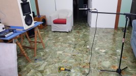
I placed the MTM on a table such that the the middle point of the tweeter is at half room height level. So ceiling and floor reflections are equidistant. I have an absorption panel on the floor to reduce intensity of that reflection.
The ceiling is 1.2 away from the tweeter midpoint. The bounce from the top midrange and back to the mic will travel 2.7m, or 7.9ms. I set FDW at 5 cycles in REW so all reflections above 650Hz will be gated out of the measurement. Is this ok or too small?
The mic is at 1m from the tweeter mouth. I marked on the floor at 15 degree intervals and 1m radius. You can see the first picture shows the blue marking on the floor and the thread marked at 1m, with the angle measurement at the point below the center of the baffle.
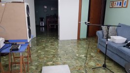
You can see the white panel door opened so to avoid the right reflection. The mic is 2m away from back wall, and baffle 1.8m away from front wall. So in the middle of the room.
Next up: measuring on vertical axis and at different horizontal angles every 15 degrees.
For vertical measurements I plan to bring the mic down (since I have the absorption panel) and towards the opened white panel doors.
Feedback?
Attachments
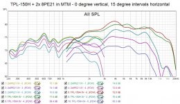
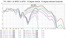
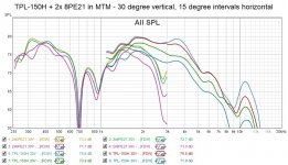
Did some measurements today. Attached the ones at 0, 15, and 30 degrees vertical and 0-60 degrees horizontal.
Pretty significant nulls at 15 and 30 for the twin 8" before the planned xo at 1600Hz. On the horizontal looks good, though.
Pretty significant nulls at 15 and 30 for the twin 8" before the planned xo at 1600Hz. On the horizontal looks good, though.
Attachments
Your third plot shows a null at 700Hz...
If you think this means 50cm difference between the mids then this would only happen at 90 degrees (guessing the distances by looking at the photo).
It must be something else, maybe the floor. Your pad is not enough to absorb 700Hz.
If you think this means 50cm difference between the mids then this would only happen at 90 degrees (guessing the distances by looking at the photo).
It must be something else, maybe the floor. Your pad is not enough to absorb 700Hz.
Your third plot shows a null at 700Hz...
If you think this means 50cm difference between the mids then this would only happen at 90 degrees (guessing the distances by looking at the photo).
It must be something else, maybe the floor. Your pad is not enough to absorb 700Hz.
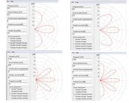
Attaching X-dir simulations of the double woofers playing alone. In X-di, driver distance is the midrange center to center distance to the tweeter, correct? In my case c-t-c is 45cm (close to you estimated 50cm!).
Looking at the first graph at 700Hz: the vertical lobe is as atrong as direct sound. In my experiment, when my mic was at 30 degrees below the tweeter that means the floor bounce had a 60 degree incidence angle (vs tweeter horiz) which we can see in X-dir has same intensity as direct sound. That sound traveled 184cm to bounce on the floor and get to the mic and took 5.4ms to get there. At 7 FDW, at 700Hz the gate is at 10ms, so the floor bounce must be it and as you say the panel used doesn't seem to be absorbing enough at those frequencies.
Coincidentially, at 15 degrees the null is at 1400Hz, double the frequency showing null at 30 degrees.
So most probably this is a measurement artifact. What should I do?
Attachments
[I have made a mistake. Of course 50cm is a wavelength at 700Hz, not a half wavelength 😱]
Building the tweeter to be narrow at the cross, and getting the woofers closer.. this is the challenge of horn MTM. I am thinking two things, one is to use a more shallow slope when you cross so you share and smooth out the problem, and you can use your polar measurements in a crossover simulator that calculates power and shows the combined polars. The other is to manage your verticals with room treatments.
Compared to the tweeter, between 1-2kHz, the woofer is more wide in the horizontal and more narrow in the vertical. Maybe this is a place you can cross because it averages out (and maybe it is difficult to run the tweeter lower).
Simulation like this is helpful. Did Bills program expect you to use 225mm instead of 450mm?at 90 degrees
Building the tweeter to be narrow at the cross, and getting the woofers closer.. this is the challenge of horn MTM. I am thinking two things, one is to use a more shallow slope when you cross so you share and smooth out the problem, and you can use your polar measurements in a crossover simulator that calculates power and shows the combined polars. The other is to manage your verticals with room treatments.
Compared to the tweeter, between 1-2kHz, the woofer is more wide in the horizontal and more narrow in the vertical. Maybe this is a place you can cross because it averages out (and maybe it is difficult to run the tweeter lower).
[I have made a mistake. Of course 50cm is a wavelength at 700Hz, not a half wavelength ]
Glad you called it out! I made the same mistake!! So my explanation would actually address the 1400Hz null. This would be good news because it's in the xo region but would seem like a measurement artifact, right? How can I confirm/test this?
Simulation like this is helpful. Did Bills program expect you to use 225mm instead of 450mm?
The weakness in X-dir is the lack of a help function. I searched online and found references to being the c-t-c from woofer to tweeter in an MTM setup. But nothing really from the author. Over at Parts Express tech talk forum member fpitas "seasoned veteran" said so. Is he right? Dunno.
Building the tweeter to be narrow at the cross, and getting the woofers closer.. this is the challenge of horn MTM. I am thinking two things, one is to use a more shallow slope when you cross so you share and smooth out the problem, and you can use your polar measurements in a crossover simulator that calculates power and shows the combined polars. The other is to manage your verticals with room treatments.
Interestingly, I'm waiting for the covid lockdown to go away so it's safe to bring a contractor to instal some treatments and paint the living room. The ceiling will be covered with bass traps and wideband absorption. So in the future the ceiling reflection will be less of an issue.
Generally, people in the room would have their heads in the 0-15 degree vertical angle.
Compared to the tweeter, between 1-2kHz, the woofer is more wide in the horizontal and more narrow in the vertical. Maybe this is a place you can cross because it averages out (and maybe it is difficult to run the tweeter lower).
It is! I'm aware of commercial speakers doing MTM with two 8" and TPL-150H (or alike) that cross at 1600Hz or so. Hence this is my starting point, now confirmed with measurements. The tweeter shouldn't be crossed below 1100Hz per the manufacturer (at 80W rated power, which I won't ever apply).
Last edited:
Can you upload these rew files?
Which ones? There are 28 files. Attaching the series at 15 degrees vertical.
Attachments
If you look at the null at 700Hz, then one at 1400Hz it looks like they are related, but maybe this is wrong? Xdir will show that the null happens at different angles with different frequencies.So my explanation would actually address the 1400Hz null. This would be good news because it's in the xo region but would seem like a measurement artifact, right? How can I confirm/test this?
If you measure every 5 degrees instead of 15 degrees maybe you will find nulls at more frequencies? You could try only 0 Horizontal, and different Verticals.
Are you going to use a crossover with 90 degrees phase difference for the MTM?this is my starting point,
Which ones? There are 28 files. Attaching the series at 15 degrees vertical.
files are 15 vertical 0-60 horizontal, no timing reference.
so you want to reference angle to be 15deg vertical?
https://kimmosaunisto.net/Software/VituixCAD/VituixCAD_Measurement_Preparations_REW.pdf
If you measure every 5 degrees instead of 15 degrees maybe you will find nulls at more frequencies? You could try only 0 Horizontal, and different Verticals.
I can measure at 5 degree increments over the weekend.
Are you going to use a crossover with 90 degrees phase difference for the MTM?
mmm...using Acourate to derive linear phase digital crossovers...don't know what phase difference is?
FWIW, they will be time-aligned, if that means anything to your question.
files are 15 vertical 0-60 horizontal, no timing reference.
so you want to reference angle to be 15deg vertical?
https://kimmosaunisto.net/Software/VituixCAD/VituixCAD_Measurement_Preparations_REW.pdf
I haven't decided what the reference angle I want it to be. What's your view?
Thanks for the link. I downloaded the software and went over the manual, but not clear which part of the REW setup manual you were referring to?
You mentioned using the MTM configuration to achieve even vertical coverage. This does not work with linear phase.
If collecting all the data correctly seems frustrating you can do like 1.6k crossing at your choosen slopes, eq and timing what you want and then measure whole speaker at once. Then you dont have to think about timing references.
It is true after all
It is true after all
You mentioned using the MTM configuration to achieve even vertical coverage. This does not work with linear phase.
I see. There are the Horbach-Keele linear phase crossovers that were developed exactly with this purpose in mind. The issue in my case is the size of the tweeter, but will try them as an alternative.
The root driver for me seeking MTM is really increased sensitivity for the midrange, yet knowing there will likely be vertical lobbing. I have noticed MTM with a tweeter this size and 8" midranges, and some knowledgeable folks saying with "enough" distance wave fronts integrate well, so I'd like to test it. Do you think it's a lost cause if implementing linear phase xo?
If collecting all the data correctly seems frustrating you can do like 1.6k crossing at your choosen slopes, eq and timing what you want and then measure whole speaker at once. Then you dont have to think about timing references.
It is true after all
I'm willing to measure to collect the data correctly! I think 😱
Well, I can't be certain since I'm not sure what I'm committing to, but the intent is here!
What would "collecting all the data correctly" entail? Can do that over the weekend.
Apparently the timing reference is important. In the past I used it when measuring L & R speakers, but here I'm using one channel for the tweeter and the other for the midrange, so I thought it didn't make sense to use a timing reference.
To simplify the measurement setup I'm using a laptop with REW connected thru USB to a Tascam US122mkII connected thru RCA to a stereo amp. And the Tascam is connected to a Dayton EMM-6 measurement mic. The Tascam is two-channel so I use one into the tweeter and the other into the midrange for these measurements.
For playback I run Roon (running digital xo) in a PC connected through ethernet to an optimized audio PC connected to a Lynx Hilo through USB. The Hilo is set up as needed to output to the different amps, and if I wanted to measure the test speaker using REW it would be complicated to adjust the Hilo settings/routing for measurements and then set it back for playback. Hence the simplified approach wth the Tascam.
It isn't so much the linear phase, but the relative phase. If you vary the phase between the three drivers, particularly between the tweeter and woofers, you can change the lobing pattern. Some ways will give you the most sensitivity but more obvious lobing, or you can go for smooth vertical coverage.
- Home
- Loudspeakers
- Multi-Way
- Lobing in MTM with TPL-150H and 8PE21