You need to increase amplification.
You could use a darlington for Q3.
I don't know what R1 is for. Can't see it improves anything.
You could use a darlington for Q3.
I don't know what R1 is for. Can't see it improves anything.

Is R1 for start-up?
I agree with above, you need more gain in the loop.
That's why a superreg has an opamp ;-)
In your circuit, Rc and Re are about equal. That limits the gain.
Try to increase Rc and decrease Re. That will give immediate benefits.
Jan
I agree with above, you need more gain in the loop.
That's why a superreg has an opamp ;-)
In your circuit, Rc and Re are about equal. That limits the gain.
Try to increase Rc and decrease Re. That will give immediate benefits.
Jan
R2 is for start up, R1 biases the Zener diode. The current through the Zener mostly comes from the regulated supply, giving better line regulation than when all the current comes from the unregulated supply.
Connect a diode in series with R2.
Add a 1.2K BE resistor to Q3.
This should already improve matters greatly; if you find it insufficient, we can discuss other options
Add a 1.2K BE resistor to Q3.
This should already improve matters greatly; if you find it insufficient, we can discuss other options
thanks for the suggestions - i will try them out.
are you refering to Rc = R6/RV1 Re = R7 ?In your circuit, Rc and Re are about equal. That limits the gain.
Try to increase Rc and decrease Re. That will give immediate benefits.
Since your Vout is ten volts greater than your Vin, you have more than enough voltage headroom to use a series pass transistor in the "common collector" (a/k/a "emitter fofllower") topology. This will reduce your output impedance enormously. Since Delta_Vout is equal to Delta_Iout times OutputImpedance, lower OutputImpedance will give you much lower Delta_Vout. And that means much better load regulation.
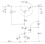
I suggest you try something like a stripped down, simplified version of the old OLD "Pooge 5.51" regulator from Audio Amateur magazine. As other members have said, you need lots more gain around your feedback loop. And thanks to the very large ratio (collector_impedance / emitter_impedance) of transistor Q2, this circuit has lots of gain. Since it's an emitter follower, it also has extremely low output impedance.
You can use whatever Constant Current Source you like: JFET, or PNP+2x1N4148, or PNP+LED, whatever you want.
_
Attachments
This is not true....
In your circuit, Rc and Re are about equal. That limits the gain.
Try to increase Rc and decrease Re. That will give immediate benefits.
Jan
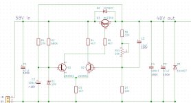
A suggestion.
C4,R6 and D3 gives a startup pulse.
After this D2 will take over from the output.
TIP115 Darlington increases the gain.
From 15mA to 30mA load is a difference of 0.006V.

C4,R6 and D3 gives a startup pulse.
After this D2 will take over from the output.
TIP115 Darlington increases the gain.
From 15mA to 30mA load is a difference of 0.006V.
Having a common emitter or common collector pass transistor doesn't fundamentally change the performance level: in both cases, the overall loop gain can be the same, provided the two configurations are used to their best optimum.
Adding active components will improve performance, if used effectively and sensibly, but great improvements are already possible with just the basic scheme, without any additions, just by tweaking the components values
Adding active components will improve performance, if used effectively and sensibly, but great improvements are already possible with just the basic scheme, without any additions, just by tweaking the components values
Correct Marcel, I deleted my post ;-)
Good morning BTW.
But there is a lot to gain by increasing R2, maybe replace with a current source.
Jan
Good morning BTW.
But there is a lot to gain by increasing R2, maybe replace with a current source.
Jan
In the original circuit of post 1, input impedance of Q3 is the load impedance for Q1
and it can not be "improved" by adding a current source (or resistor) in parallel.
Show me a current source which works with 0,6 V ..
and it can not be "improved" by adding a current source (or resistor) in parallel.
Show me a current source which works with 0,6 V ..
You paint yourself in a corner by using a PNP. If you use an NPN you can use current source biasing as in the superreg concept.A suggestion.
C4,R6 and D3 gives a startup pulse.
After this D2 will take over from the output.
TIP115 Darlington increases the gain.
From 15mA to 30mA load is a difference of 0.006V.
View attachment 1263863
You need to swap the LTP outputs for correct loop phase and Bob's your uncle ;-)
Jan
The structure of the schematic in post 1 is not too bad and is used
in some "negative" regulators as well as in low drop-out circuits.
in some "negative" regulators as well as in low drop-out circuits.
Yes.You paint yourself in a corner by using a PNP. If you use an NPN you can use current source biasing as in the superreg concept.
You need to swap the LTP outputs for correct loop phase and Bob's your uncle ;-)
Jan
The only advantage of PNP is the low dropout.
If you can accept a few volt dropout like in supereg it is to prefer NPN.
- Home
- Amplifiers
- Power Supplies
- load regulation