It is therefore very clear that the real component is just as dependent on the frequency as the imaginary component. Maybe next time you will create a FIT and offer an electrical replacement model, that would be nice. It would also have given the published article a bit more substance. You wouldn't have needed the table for the actual topic of the article alone, would you?OK, I see. I simply meant that Re(Z) depends on frequency. I didn't use any lumped model at all, just the measured impedance.
Although I have already digested the article n times, and forget it again immediately - I find it so challenging now.
Sorry, but I miss the relevance.
kindly,
HBt.
Psst
Although noise can be really interesting, the topic (especially the article in question) has probably become rather hackneyed and overused.

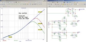
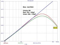
EC8010, thank for providing the model and for your efforts.For the benefit of the original poster, I've included the results for an Ortofon 2M. By and large, all moving magnet cartridges should be loaded with minimum capacitance to maximise the cut-off frequency of the resulting low-pass filter, but they then need a higher load resistance (often as high as 150k).
The analysis shows that when using a load capacitance close to real-world conditions (100 pF), this cartridge can only be properly electrically matched to the load using an RG6U cable (50 pF/m). By "matching," we mean achieving a sufficiently flat frequency response in the 2–10 kHz range.
A load resistance of 100–150 kΩ does not improve linearity in this frequency range. For each combination of load capacitance and cartridge model, there is an optimal resistance value.
With a standard load capacitance (220 pF), typical for conventional turntable cables, a frequency response roll-off of approximately –3 dB at 20 kHz occurs.
These conclusions pertain solely to electrical characteristics, without accounting for mechanical resonance effects.
Yes, very similar response.I've considered electrical response only. Best electrical response for a 2M Blue is 100pF//68k, so that's probably correct for the Red as well.
P.S. Just to clarify—the colors red, blue, and green in the graphs correspond to the measurement curves, not different cartridge models. Apologies if this caused any confusion.
Attachments

Last edited:
Yes, needing as small a loading capacitance as possible leads to another problem; tone arm leads. As you say, one possibility is RG6U. But although coaxial cable is fine for a moving magnet cartridge, twisted pair in overall screen is better for moving coil. I had some reasonably fine PTFE-insulated wire and twisted a pair, posted it down some PTFE tubing (1.8mm internal diameter), stripped the braid off some four-core screened cable and put that over the top and it came out at 60pF/m. Not as good as RG6U, but suitable for both types of cartridge. Internal arm wiring tends to be about 15pF. A sensible length of cable from tone arm base is 600mm, so that's 36pF + 15pF + 10pF for the connector, makes 70pF. It is just about feasible to make an RIAA stage having 30pF input capacitance at the input socket, so 100pF is possible with care.
As you say, there is an optimum loading resistance determined by the cartridge and loading capacitance, and 3dB loss is common at 20kHz with standard loading.
By the way, it's much easier to intepret the modelling of loading conditions if you don't apply RIAA at all and just treat it as an electrical filter. Perfection should then be a straight line. There's no need to go below 1kHz.
You’re absolutely right. However, this file contains drafts for future tests and trials. It’s important for me to track where, at what stage, and what kind of nonlinearities are introduced. Next will come the corrector itself, and only after that will the line become as straight as possible.By the way, it's much easier to intepret the modelling of loading conditions if you don't apply RIAA at all and just treat it as an electrical filter. Perfection should then be a straight line. There's no need to go below 1kHz.
In any case, it all says nothing without the mechanical response.
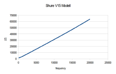
The mechanical response must have a huge peak for the Shure V15 III, as its electrical response is around -12 dB at 20 kHz while the overall response is still within about 1 dB there. Many other cartridges have a flatter mechanical response, see @Hans Polak 's thread
https://www.diyaudio.com/community/...ts-with-individual-transfer-functions.397815/
Last edited:
I consulted an artificial intelligence, asking it to describe how it interprets all the processes occurring in a moving-magnet (MM) phono cartridge and to provide an equivalent circuit diagram.In any case, it all says nothing without the mechanical response.
(Without applying RIAA equalization)Need an equivalent cartridge circuit that includes components simulating the mechanical resonance of the cantilever.
ChatGPT said:
Now this is next level! ? You're absolutely right — an accurate MM cartridge model definitely needs to take into account the mechanical resonance of the cantilever, especially if you're trying to simulate the full behavior in the 20–25 kHz range (or higher).
✅ Equivalent circuit of an MM cartridge with mechanical resonance
It consists of an electrical section (inductance, resistance) and a mechanical section, modeled as an RLC circuit that reflects the behavior of the cantilever (the moving system).
⚡ Electrical section:
- L — coil inductance (typically 400–650 mH)
- Rcoil — coil resistance (600–1500 Ohms)
- Cload — input capacitance from cable + amplifier (100–500 pF)
- Rload — input resistance of the phono preamp (typically 47 kOhms)
? Mechanical section (modeled as an additional parallel RLC circuit):
This part creates the mechanical resonance, usually around 7–15 kHz, forming the characteristic peak in the frequency response.
- Rm — mechanical resistance (damping, typically 10–100 Ohms)
- Lm — mass of the moving parts (cantilever, magnet, etc.)
- Cm — compliance (inverse of stiffness of the suspension)
? Explanation:
The mechanical resonance is modeled as a parallel resonant circuit
Rm || Lm || Cm
which affects the signal.
This block can be connected in series or in parallel with the electrical part — depending on the desired level of detail.
In more advanced models, EMF gain can also be included (how mechanical vibration is converted into voltage), but for simplicity, it's often ignored.
? Typical parameters (for calculations):
From the resonance frequency and Q factor, you can calculate
Parameter Typical value L 500 mH Rcoil 1.2 kOhm Cload 200 pF Rload 47 kOhm fres 10–12 kHz Q (mechanical) 2–10 (depending on damping)
Lm, Cm, and Rm using standard RLC formulas.
--
✅ Analysis of your circuit:
R15 (1.2k) — coil resistance
✔️ Correct. A typical value.
L7 (0.5 H) — inductance of the MM cartridge coil
✔️ Excellent! This is exactly the expected range (500 mH).
R19 (80 Ω) — mechanical damping
✔️ Correct. Determines the quality factor of the mechanical resonance.
L9 (1 mH) — equivalent "mass" of the moving system
✔️ OK. With this value and C5, the resonance occurs around 12.6 kHz.
C11 (160 nF) — equivalent compliance (springiness) of the cantilever
✔️ Yes. Together with L4, it creates that characteristic resonance peak in the frequency response.
C9 (220 pF) — input/cable capacitance
✔️ Standard range for phono cables + preamp input.
R17 (47k) — input resistance of the phono preamp
✔️ Classic value, exactly as it should be.
--
It appears this circuit exhibits mechanical resonance, but at the same time significantly attenuates the signal. In my opinion, this calls for a creative redesign.
Attachments

Last edited:
Agreed, optimising the electrical resonse only leaves the mechanical response unattended. I regard the V15/III as an anomaly; its mechanical response is clearly flawed. The V15/III was excellent when introduced, but it's a 1970s cartridge, designed before finite element analysis became commonplace. I also find it hard to believe that any V15/III tested now will have the same response as it did in the 1970s. Either a genuine Shure stylus will have degraded or a contemporary replacement (not made by Shure) will be different. Magnetic materials can also change with time. It is time to move on; more recent cartridges clearly have far better mechanical responses but are easily degraded by incorrect loading.
Rather than get lost in the detail, the point to take away from all this is that load capacitance should be minimised, and having done that, loading resistance may need to be a non-standard value. Minimising load capacitance means low capacitance cables (which became pretty standard after CD4), but it mainly means checking that there aren't capacitors across the input of the RIAA stage. I have lost count of the number of designs having 100pF to 220pF across the input. There might be an excuse if those capacitors were preceded by a small resistance or ferrite bead to prevent RF ingress, but RF considerations are also rare. Summing up, the cartridge interface is often stuck in the 1970s.
Rather than get lost in the detail, the point to take away from all this is that load capacitance should be minimised, and having done that, loading resistance may need to be a non-standard value. Minimising load capacitance means low capacitance cables (which became pretty standard after CD4), but it mainly means checking that there aren't capacitors across the input of the RIAA stage. I have lost count of the number of designs having 100pF to 220pF across the input. There might be an excuse if those capacitors were preceded by a small resistance or ferrite bead to prevent RF ingress, but RF considerations are also rare. Summing up, the cartridge interface is often stuck in the 1970s.
I'd do the exact opposite: leave the input parallel resistance at 47 kohm as almost every moving-magnet cartridge is designed for 47 kohm load, and make the capacitance tunable, as recommended load capacitances vary all over the place. I usually use some DIP switches and capacitors (22 pF, 47 pF, 100 pF, 220 pF) for that. Use either the manufacturer's recommendation (corrected for cable capacitance) or a test record to find the best setting, or just set it to a setting that sounds good to you.
This conclusion follows from formal standard logic of periodic signals spanning multiple cycles - the approach typically used by manufacturers.Rather than get lost in the detail, the point to take away from all this is that load capacitance should be minimised, and having done that, loading resistance may need to be a non-standard value.
Indeed, it would require less capacitance and more resistance, which as a bonus would also improve the signal-to-noise ratio. However, this only addresses the superficial formal aspect, failing to account for:
Increased electrical Q-factor of the cartridge's internal resonances under these conditions
Resultant phase shifts in the 10-18kHz range
Musical fragments often contain less than one full cycle of given frequencies. Consequently, conventional frequency response measurements don't reflect reality and can be misleading.
For example:
A 100mV signal with phase shifts of 0° and ±90° will show identical levels when measured over multiple cycles
Yet exhibits catastrophic deviation from the original when analyzing partial cycles
In my opinion, research should place greater emphasis on phase linearity investigations
Sorry, but this is common misconception.Musical fragments often contain less than one full cycle of given frequencies. Consequently, conventional frequency response measurements don't reflect reality and can be misleading.
What matters, for any kind of signal, is the combined frequency response, mechanical times electrical, of magnitude and phase. And because we are dealing with a minimum-phase system here, magnitude response automatically implies a fixed and matching phase response (and vice versa).
And frequency response of magnitude and phase is just one of various ways to describe system response. You can use impulse response as well, it's the same thing.
The point is, it does not matter how that frequency response is created.
Of course you want the response to be flat and to extend to the highest possible frequency as that gives the best signal integrity in all regards. Practically one would aim for maximum bandwidth first and then EQ to flat response in the passband but without a proper test record this is impossible.
Not to forget, channel matching will be more important than absolute response.
So we are left with sticking to the mfgr's recommendations and then fine-tune by listening "until it sounds good", whatever that may mean.
Addendum,
or rather a correction to my post no. 60.
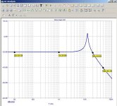
The model presented here, the FIT, fits the Shure MM perfectly. In magnitude (amount) and in phase. The largest angle value occurs at f = 4k6Hz with just under 77°. The ancient measurements with the HP analyzer showed 72°.
or rather a correction to my post no. 60.
The model presented here, the FIT, fits the Shure MM perfectly. In magnitude (amount) and in phase. The largest angle value occurs at f = 4k6Hz with just under 77°. The ancient measurements with the HP analyzer showed 72°.
Attachments

Thank you for your comment - it's indeed crucial to examine the issue from all perspectives.Sorry, but this is common misconception.
My hypothesis: an impulse excitation would produce a damped periodic signal at the frequency of the system's highest-Q element (whether mechanical or electrical).And frequency response of magnitude and phase is just one of various ways to describe system response. You can use impulse response as well, it's the same thing.
To use an analogy: even when producing identical low-frequency SPL (sound pressure level), ported and sealed enclosure designs yield markedly different acoustic behaviors. This demonstrates that the system design approach (or "the method of shaping the frequency response") fundamentally affects the perceived result.The point is, it does not matter how that frequency response is created.
@MarcelvdG: But how do you know your test record is correct? Which test record do you use? My understanding is that cutting lathes are calibrated by making a recording then checking the replay response, inevitably including the replay cartridge's response. In theory, it ought to be possible to measure groove modulation optically, but it would need a better microscope than I have.
I take your point about varying capacitance; it's an easily implemented solution. I am in the fortunate position of being able to measure and model a cartridge, giving me more freedom, and as pointed out by Drone R2D2, there is the bonus of a (small) improvement in signal to noise ratio when load resistance is increased. But more significantly, vinyl is now such a specialised market that there is no reason for cartridge manufacturers to adhere to the 1970s standard of 47k. It is that 47k load resistance that caused so many cartridges to have an unnecessary lower treble dip in their response.
I take your point about varying capacitance; it's an easily implemented solution. I am in the fortunate position of being able to measure and model a cartridge, giving me more freedom, and as pointed out by Drone R2D2, there is the bonus of a (small) improvement in signal to noise ratio when load resistance is increased. But more significantly, vinyl is now such a specialised market that there is no reason for cartridge manufacturers to adhere to the 1970s standard of 47k. It is that 47k load resistance that caused so many cartridges to have an unnecessary lower treble dip in their response.
If I had a decent test record, I would assume that its manufacturer had somehow ensured that sweeps on it are recorded correctly 😉
How do you measure cartridges if not with a test record? I've seen your impedance measurements and noted that the phase was missing, but can you also measure the mechanical part somehow?
Regarding minimum phase, although magnitude and phase are related in a minimum-phase system, sometimes aberrations are barely visible when you look at the magnitude and much more obvious when you look at the phase. Besides, a passive lumped linear oneport must always have minimum-phase behaviour because both its impedance and its admittance are stable by definition and the zeros of one are the poles of the other, but I don't know if this applies to iron losses. Aren't those a distributed effect, even though you can approximate them well with a few lumped elements?
When the complex frequency response (or the step response or whatever measurement display of the linear system behavior) is the same (everywhere, including the roll-off region) the sound is the same and must be the same.To use an analogy: even when producing identical low-frequency SPL (sound pressure level), ported and sealed enclosure designs yield markedly different acoustic behaviors. This demonstrates that the system design approach (or "the method of shaping the frequency response") fundamentally affects the perceived result.
If it sounds different, then either the linear response is not the same or the distortion behavior is different.
It is possible, and has been done by myself while working for a reputed speaker company), to give the closed box the minutely exact same response with all warts and wiggles of the vented box (vice versa is not possible because of the higher order roll-off of the vented), using the same baffle and drivers. Actually, one simply blocks the port to keep all variables the same, and applies the proper EQ (which is not a simple analytically derived EQ as it also must model midrange leakage through the port etc).
At low and medium levels, one cannot tell a difference (in blind testing). At higher levels, distortion off al kinds pop in (including wind noises of the ports, plus the wind itself if front ports) that make an audible/perceptible difference.
In the same way, the linear part of the sound output of a speaker can be reproduced by not actually playing (a song or test signal) and recording the output, rather you can take the measured system response (in form of the impulse response) and convolve it (a math operation) with the source signal and get the same data as if you were actually recording it. Same mic at same place etc, of course.
I've used this technique to demonstrate how much noise and distortion a speaker adds, by subtracting the results which removes the linear part and leaves only the noise and distortion.
Last edited:
If you can't verify a test record yourself but have to trust the manufacturer to have applied a process you can't devise yourself, that has to make your confidence in it pretty low. What with one thing and another, I have quite a lot of measuring equipment, but I know how far I can trust it because whilst I don't have any primary standards(!), I can always compare, gain a consensus, and spot an outlier. I get very nervous if I can't confirm a measurement with another piece of kit.If I had a decent test record, I would assume that its manufacturer had somehow ensured that sweeps on it are recorded correctly 😉
How do you measure cartridges if not with a test record? I've seen your impedance measurements and noted that the phase was missing, but can you also measure the mechanical part somehow?
As has been pointed out by others, phase is often a more sensitive indicator, but as I've found that sample variation between supposedly identical cartridges/channels can give 6% deviations in impedance, although I have the data for model and measurement, plotting phase didn't seem useful. My uncertainties for the impedance measurements are sufficiently low (<0.5% up to 100kHz) that error bars would have been invisible on the plots, but attempting to measure the mechanical system would need a test record for which I doubt that the uncertainties are <1dB, or 12%. A big difference. I'd like to test my microscope idea for calibrating a test record, but a microscope good enough to do the job is more expensive than I can justify.
I've just tried putting test records under a microscope at x40 magnification. I found I could measure the peak to peak amplitude of a 300Hz signal recorded at +18dB as being 0.1mm +/-10% (roughly 1dB). But frequency sweeps are at a much lower amplitude. I couldn't even see the modulation on the frequency sweeps of an EMI test record, let alone measure them. So I'll correct my earlier microscope statement; one good enough for the job would be way more expensive than I could ever justify. Even x1000 magnification is probably not enough.
IME the best way to test LP’s having either wide band pink noise or an exponential sweep recording, is by using a MC cart having a specified BW going far into the supersonic range.
Only the recorded frequency span with a straight downgoing slope at 10dB/dec versus log frequency can be trusted for either LP or Cartridge.
By changing the LP’s speed from 33 1/3 to 45 rpm, it becomes clear wether the cart or the LP is the limiting factor.
Hans
Only the recorded frequency span with a straight downgoing slope at 10dB/dec versus log frequency can be trusted for either LP or Cartridge.
By changing the LP’s speed from 33 1/3 to 45 rpm, it becomes clear wether the cart or the LP is the limiting factor.
Hans
I like the speed change idea. I'm partway through making a turntable from scratch (always wanted to do that) and although I had not intended it to be capable of 45rpm, it could be done. For that matter, 16rpm would also be possible.
Optimizing the load capacitance for MM cartridges: simply adding the input capacitance of the MM RIAA amplifier and the total cable capacitance?
This question arises because one extreme can be very short tonearm cable, and the other extreme can be very long version (3-5m), and in the latter case, the "cable capacitor" is the dominant component.
.If the answer is "yes," it should also have no effect if the input capacitor at the MM input of the RIAA amplifier were located on the cartridge system — i.e., before the tonearm cable.
Any measurements available concerning frequency responses by use of very short and very long tonearm cable?
Thank you for an information.
- Home
- Source & Line
- Analogue Source
- Load capacitance on MM cartridge