The ones with discrete output stage i've tried (LME49810 & LM4702 sound very, very good). Gainclones don't sound ugly but i don't love them. I would describe the LME49810 as vibrant and well-proportioned, drums kick in a precise manner and female voices really shout, maybe in a slightly harsh manner despite this may well be because i'm not used to such an "unveiled" presentation.
It's worth building it!
This question has been asked a lot and no one has post a single reply. I'm not an audio reviewer and some virtues and faults could come from source/loudspeakers/room and not the amplifier itself. LM3886 has a slight haze in the bass, while LM4562 has the same at the highs. LME49810 is well proportioned in the same setup so i belive the comparison is fair.
monkey29
Can you share the sch?
I will like to try 49830 but with 4 pairs of sk1058/sj162 on +/-68V.
Thoughts?
Can you share the sch?
I will like to try 49830 but with 4 pairs of sk1058/sj162 on +/-68V.
Thoughts?
felixx said:monkey29
Can you share the sch?
I will like to try 49830 but with 4 pairs of sk1058/sj162 on +/-68V.
Thoughts?
Proposes to add a drive and to drive 4 pairs of sk1058/sj162
"Can you share the sch?"
LME49810 or 830?
I think LME49830 can drive 4 pairs of laterals without any other "predriver".The 810 maybe not.
I'm thinking to replace the semi R bias with fixed resistor and also without TIP 31 ...considering laterals.
I'm thinking to replace the semi R bias with fixed resistor and also without TIP 31 ...considering laterals.
felixx said:I think LME49830 can drive 4 pairs of laterals without any other "predriver".The 810 maybe not.
I'm thinking to replace the semi R bias with fixed resistor and also without TIP 31 ...considering laterals.
power amplifier of MOSFET with the input capacitance great, if parallel more devices, will add to the burden of LME49830.
I have tested the LME49830 driving two pairs of 2SK1530/2SJ201 and 2SK1058/2SJ162 directly or with an extra current gain stage. The only difference I could measure was less output power with the extra stage because of the loss of voltage to the gate at the FETs. High slew rate (35-40V/us) was possible with either design. I don't know what would happen if you go to 4 pairs but you can look at the differnt datasheets for for the above parts and compare gate capacitance to see what you might be able to figure. Or add the footprint for an extra stage to your PCB and either use it or jumper it to test. Easy enough to do.
-SL
-SL
SpittinLLama
O.K.
Now... who did a "face to face" comparing test with this chips and discrete drivers with the same power trz.?
If sonicaly make good impression maybe it's worth to try to write some words about the setup and why not to go further and comparing with something $$$$.
In some terms,the most of the chip drivers have lack on details and something missing on the bottom and upper bandwith.
However, excellent, thd, imd, tid measurements do not always tell the whole story about how an amplifier will or will not alter the sound signals than pass through it.
I have on the bench an discrete amp (bjt's follows by 4 pairs laterals) and my fingers burn's me to try this chip.
I feel that the LME49810 with 2SK1530/2SJ201 (assuming good layout bypassed electrolytics, no caps on the signal path and my "trick": placing a snubber on each power transistor's drain) is one of the most detailed amplifiers i've ever heard. With IRFP ones it's more warm in a way that reminds me slightly of the new ipod's retail earbuds. I don't know how it compares to anything expensive since i really prefer to invest the time needed to earn the money that these cost in building mine! But being such a wide range of available driver ic's nowadays it would be nice to read sonic feedback from builders before deciding the way to go.
felixx said:In some terms,the most of the chip drivers have lack on details and something missing on the bottom and upper bandwith.
I haven't found that to be the case with the LM4702 -- I have used both to power a pair of S1-EX* spkrs and they certainly are not lacking in the bass, nor in terms of transparency...same is true of my Beveled Thors driven by the LM4702 and lateral mosfets -- but the Thors can't quite handle all the power that the Pioneers can.
FWIW, I use a pair of lateral MOSFETs on each channel, no VBE transistor with the bias set at 115mA. I have an oversized toroid transformer and 39mF per rail...and WIMA decoupling caps.
Try running your amplifier without the input coupling cap...
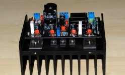
This is my amp (4 x 22000uf/100V BHC Aerovox/1kw transformer)...and maybe I will try these chip's ...will see....
http://www.diyaudio.com/forums/showthread.php?postid=1310471#post1310471
These are my speakers:
http://www.diyaudio.com/forums/showthread.php?postid=1194102#post1194102
Anyone tryed UPC2581V?
It was used in Sony receivers but I can't find data sheet.
http://www.diyaudio.com/forums/showthread.php?postid=1310471#post1310471
These are my speakers:
http://www.diyaudio.com/forums/showthread.php?postid=1194102#post1194102
Anyone tryed UPC2581V?
It was used in Sony receivers but I can't find data sheet.
ionomolo, what values do you use for the subber from the drain on each FET? Is that drain to GND? In the big BJT vs MOSFET thread that Bob Cordell started he talked about a snubber from gate to drain and one from gate to GND like his paper showed. I am just curious if I can increase stability with such additions so I can reduce the Comp cap further to get higher SR.
I wish I had some expensive all discrete amps but too poor for such things 🙁 I'd love to do some sound comparisons. To me the LM4702, LME49810, etc have good sound, very clear, very defined but I don't know that I am much of a listener. Something you have to try for yourself. Maybe some will that also have some great discrete amps.
-SL
I only use drain to gnd with 0.1uF + 2R2. I also use gate to source clamping at much less than breakdown voltage to get short-circuit current limiting. I don't feel the need for additional snubber since it's stable at 50V/usec slew rate and probably slightly more.
I've never had any stability issues with simple mosfet output stages, only with mosfet-Sziklai ones.
I've never had any stability issues with simple mosfet output stages, only with mosfet-Sziklai ones.
Thanks for the info. I don't have much oscillation problems but using the LME49830 I can only get a slew rate of 40V/us. I can't reduce the compensation capacitor value lower to increase SR without some oscillation. Stability is pretty good with the layout and 0.1uF caps on the supply line right at the drain. The next board I do I will have to add the option for these snubbers to test. One more ?, for gate clamping do you just use something simple like a couple Zeners?
-SL
-SL
Yes, it's important to choose proper voltage so current limiting won't be set at a too low value taking care of temperature variation. This also introduces a self-limiting effect that translates into less output current when temperature increases (Assuming negative tempco at the current limit).
What i've found to be the most critical part regarding stability is the gate stopper resistor. I always place it attached to the transistor's gate and sold the mosfet with it's legs as short as possible. This makes heatsinking more difficult but provides more stability.
What i've found to be the most critical part regarding stability is the gate stopper resistor. I always place it attached to the transistor's gate and sold the mosfet with it's legs as short as possible. This makes heatsinking more difficult but provides more stability.
Thanks for all the tips and info. Someday I hope to come visit Spain, so much history and so much to see, looks beautiful in pictures.
-SL
-SL
SpittinLLama said:Thanks for the info. I don't have much oscillation problems but using the LME49830 I can only get a slew rate of 40V/us.
-SL
How are you measuring slew rate ? -- you may be measuring the slew of your pulse generator PLUS the slew of your amplifier.
(edit)
...and remember that your pulse (or sq wave) generator really wants to get terminated into the appropriate load -- my Tektronix likes to see 50 ohms.
I'll have to double check again but I think the input was faster than what the amp could do. Thanks for the reminder because this has happened before when the signal generator was too slow and I was getting wrong numbers.
-SL
-SL
- Home
- Amplifiers
- Chip Amps
- LME49810 - a new cousin for LM4702