I work on LME49830 right now...
Hmmm...
I use 4 pairs of laterals but I can't go upper than 25mA with the basic aplication.
I tryed to go lower on the RQ12K....to 2,2k and the bias is 35mA....still not enough.
I tryed to go lower...100ohms (90mA) but LME became really hot...too hot and I use a large heatsink for him.
Also I moddify the Rb1,Rb2 and Rbias to upper values and also lower values but bias can't be change.
My needs is to bias each lateral with 150mA-200mA.
Any thoughts will be appreciated.
Can you post your schematic? What FETs are you using? 4 devices per side in the output stage?
-SL
-SL

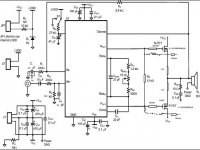
It looks like you have the gate resistors to the other FET pairs in series? Is that a schematic error? The gate resistors should all connect to the same location so each gate resistor and FET is in parallel. On the board I have with LME49830 and these FETs (2 pair) I use about 700 ohms resistance between the bias pins. I have a 620 ohm resistor with a 200 ohm pot to adjust. Using supplied of +/-60V I set the current from each supply to about 250mA. For 2 pair this is about right to get stable bias across temperature. Start with much smaller value of resistors on the bias to start with low current and then increase from there. If the FETs are not matched be sure to use a source resistor of like 0.1ohm. You might also try starting with a higher value compensation capacitor like 30pF or 47pF to be sure you have stability then reduce down as possible for best SR.
-SL
-SL
It looks like you have the gate resistors to the other FET pairs in series? Is that a schematic error? The gate resistors should all connect to the same location so each gate resistor and FET is in parallel.
Yes...I was in a rush.
On the board I have with LME49830 and these FETs (2 pair) I use about 700 ohms resistance between the bias pins. I have a 620 ohm resistor with a 200 ohm pot to adjust. Using supplied of +/-60V I set the current from each supply to about 250mA. For 2 pair this is about right to get stable bias across temperature. Start with much smaller value of resistors on the bias to start with low current and then increase from there. If the FETs are not matched be sure to use a source resistor of like 0.1ohm. You might also try starting with a higher value compensation capacitor like 30pF or 47pF to be sure you have stability then reduce down as possible for best SR.
My psu have +/-68V.I will try tomorow to change the bias values indicated and post the results.
Attachments
Hi all,
I am considering trying to put together an amplifier based on LME49810s.
I was recently given a cheapo "PA" amp with a melted transformer. I stole all of the components off the PCB, the two heatsinks, and chucked the rest. I have 6 x 2SC5200, 6 x 2SA1943 power transistors and 2 x 2SC4793, 2 x 2SA1837 driver transistors to play with.
I figured that playing with these LME driver chips would be the next logical step from 'Gainclones' for me. I have a few queries 🙂
I can mostly understand the output stage. At the very least what's happening there! But I would like some sort of SOA protection. I'm having a hard time trying to get my head around the SOA graphs. I can be a bit dense I guess. I can understand how the SOA protection I am looking at works, by stealing current away from the base of the drivers, but I would like to try and understand how to read these SOA graphs first obviously.
I intend on using three pairs of these devices per channel, and was thinking of +-60v supply rails. At VCE 60v, the DC current at Tc 25 degree's is about 2A and for 100mS about 3A. So with three pairs, I suppose this would mean 6A DC to 9A 100mS?
I believe that the cheapo amp the devices came out of was rated 800W. It had model TS-800, and I just found the same amp on ebay - seller reckons 1000W - with just three pairs per channel, and had supply rails of about +-79v. If I am reading the SOA graphs right, then I just can't see how it could manage the claimed 800W / 1000W...
With an 8 ohm pure resistive load, at 50v peak this would mean 6.25A / 312W? So I am already in trouble? Or should I be using RMS values, so 50v peak is 35vrms and this would mean 4.3A / 153W? I have a feeling I should be using RMS values...
But then this is at Tc25. I have no idea how to derate based on temperature. There's no derating figures in the datasheet that I can see. What happens if running with the heatsinks at, say, 60C. With a reactive 8 ohm load, three pairs seems about minimum for +-60v supplies? It sounds like it may already be unsafe for a 4 ohm speaker?
# SpittinLLama
It works.I use 1k pot bias series with 500ohms for 500mA bias (for 4 pairs of laterals) in series with psu.It seems ok.
What value did you use for RF 6,8k?
Do you have some fiss on the speaker on maximum power without conecting the input to the music source?
Thanks.
It works.I use 1k pot bias series with 500ohms for 500mA bias (for 4 pairs of laterals) in series with psu.It seems ok.
What value did you use for RF 6,8k?
Do you have some fiss on the speaker on maximum power without conecting the input to the music source?
Thanks.
Yes, I used the schematic pretty much on the datasheet, 6.8k for the feedback and input resistor. I don't think I had hiss on the speaker but I also didn't check with the input floating, always had it connected to a source even if the source was off. If you have a scope you might want to check to be sure there is no oscillation happening when the input is floating. I know the LM4702 will oscillate if the input is left floated but didn't check that on the LME49830. Thanks for reporting back that it is working. I'd be interested in any other observations such as sound quality, performance numbers, etc. It sounded good to me but I don't consider myself a great listener.
-SL
-SL
I'd be interested in any other observations such as sound quality, performance numbers, etc. It sounded good to me but I don't consider myself a great listener.
The sound is good.I compare with my tube triode monobloks and the LME49830 with laterals and enough bias will do the job right.I go up to 600mA for 4 pairs.The heatsink and the transformer is the limit😎 .
I choose 9k8 for Rf. and I have aprox. 306W/4 ohms and 236w/8 ohms and no signs of instability.My goal was to obtain a fast amp with high damping factor to drive the woofers into an open baffle(4ohms).
AndrewT said:Hi Kam,
you are still confusing me with your measurements of voltage units.
3A DC supply will just work for a resistive 8r0 load on a +-30Vdc supply.
For a reactive 8ohm speaker load you can have peak currents of (30-4)/8/0.35~=9.3Apk
Note: I have used a 4V loss for a short term voltage/current peak.
Is the extra 6.3A coming from decoupling capacitance downstream of the PSU?
AndrewT, Thanks for your opinion in my power supply issue. I have solved the problem. It is because of the limited driving current of my bench power supply it is just about 1A. Therefore, the amp suffer a lot of voltage drop during max swing.
Now, I have encountered another problem. Basically, I have tested my amp using a normal function generator to investigate can my amp amplify the input signal and observe the current consumption under different input amplitude with 8 ohm loading. I can have about 58V output peak to peak with +/-30V tank cap power supply and an aglient function generator.
When I want to measure the T.H.D performance of my amplifier by using the audio precision audio analyzer with either 20 ohm or max 80 ohm impedance AP signal source. My amplifier oscillates when the output peak to peak output voltage is about 42V.
I am wondering the two signal sources should be the same. Why the signal source from AP cause my amplifier to oscillate. My amplifier schematic is the same as the design with output stage in LME49810 datasheet.
Thanks for your opinions 😉
kamwing said:
AndrewT, Thanks for your opinion in my power supply issue. I have solved the problem. It is because of the limited driving current of my bench power supply it is just about 1A. Therefore, the amp suffer a lot of voltage drop during max swing.
Now, I have encountered another problem. Basically, I have tested my amp using a normal function generator to investigate can my amp amplify the input signal and observe the current consumption under different input amplitude with 8 ohm loading. I can have about 58V output peak to peak with +/-30V tank cap power supply and an aglient function generator.
When I want to measure the T.H.D performance of my amplifier by using the audio precision audio analyzer with either 20 ohm or max 80 ohm impedance AP signal source. My amplifier oscillates when the output peak to peak output voltage is about 42V.
I am wondering the two signal sources should be the same. Why the signal source from AP cause my amplifier to oscillate. My amplifier schematic is the same as the design with output stage in LME49810 datasheet.
Thanks for your opinions 😉
I have solved the problem already. Moreover, I just want to share my solution here. The oscillation arises from the thin trace ground on my design so remember to thicken the ground and power line. 2oz copper for those traces are recommended. It will solve the lack of reference problem.
Originally posted by IVANSOUND
You the rest current 2sk1058/2sj162 interests?
I'm building an amplifier with these @ 200 mA idle current (slightly above the value suggested in AN-1645), but what does your post mean exactly?
Originally posted by kamwing
which idle current can you get with a LME49810 and SK/SJ-Fets?
More than the transistor can withstand.
ionomolo said:
I'm building an amplifier with these @ 200 mA idle current (slightly above the value suggested in AN-1645), but what does your post mean exactly?
At least measured, the THD% doesn't change that much as you increase the bias above say 115 to 120 mA. You will need larger heat sinking, however.
Thanks!More than the transistor can withstand.
but why then using the LME49830 still?
I believe @ 200 mA idle current with 2sk1058/2sj162 is
really good/enough,.
Do I need the 49830 only, if I like to use HexFets?
But, theoretical, I perfer the 49810 because his Baker Clamp
I havn't already built anything with the lme49830, but i belive that both can drive hexfets (at least i did an hexfet amplifier with the lme49810 and i like it more that the one i did with 2sk1530/2sj201).
I'm powering it from a 42Vdc supply so it dissipates 10W when idling and it has large heatsinks. I plan to increase the bias to 0.5A to get passages up to 85 dB's reproduced in class A 🙂
Originally posted by jackinnj
At least measured, the THD% doesn't change that much as you increase the bias above say 115 to 120 mA. You will need larger heat sinking, however.
I'm powering it from a 42Vdc supply so it dissipates 10W when idling and it has large heatsinks. I plan to increase the bias to 0.5A to get passages up to 85 dB's reproduced in class A 🙂
maybe the best way
I'm very interested.
if you do it, please give me a feedback.I plan to increase the bias to 0.5A to get passages up to
85 dB's reproduced in class A
I'm very interested.
- Home
- Amplifiers
- Chip Amps
- LME49810 - a new cousin for LM4702