Ok rewired it up and tgis is how i've got it....
This is my transformer wiring diagram...
Technical notes: : Technical Information
I have got Red to AC1 nearest edge of board, Black AC1 Inner hole, Yellow AC2 Inner hole and Orange AC2 Edge of board.
Is this the right way?
This is my transformer wiring diagram...
Technical notes: : Technical Information
I have got Red to AC1 nearest edge of board, Black AC1 Inner hole, Yellow AC2 Inner hole and Orange AC2 Edge of board.
Is this the right way?
Got my simple bulb tester... negative and earth into block connector and live into bulb and out othr side of bulb.
Rewired transformer to amp and powered up... Light didnt light up or flicker at all. However when I put probes onto AC side the bulb is lighting up.
MMMmm I'm getting a bit !$*@%&$ angry now. Think I might call it a day and try again tomoro. Only upto rectifier, got the amps to go though yet.
Rewired transformer to amp and powered up... Light didnt light up or flicker at all. However when I put probes onto AC side the bulb is lighting up.
MMMmm I'm getting a bit !$*@%&$ angry now. Think I might call it a day and try again tomoro. Only upto rectifier, got the amps to go though yet.
The bulb should not light, or light only dimly... you may get a flash when everything is connected up and the capacitors charge. If the bulb lights up brightly and stays lit, it means something is trying to draw a lot of current, and the bulb takes the power instead. The beauty of it is that the bulb absorbs the power instead of whatever is shorted, saving the parts.
You were testing the diodes correctly - they should only conduct one way. It seems like they are OK.
The transformer wiring now sounds correct.
Start with a 60W bulb.
You were testing the diodes correctly - they should only conduct one way. It seems like they are OK.
The transformer wiring now sounds correct.
Start with a 60W bulb.
Only managed to find a 40W bulb... Power up is fine, no light, bangs or flashes.
I set my multimeter to DC, place red probe on V+ and black probe on PG+... I get a spark which freaks me out to start with... Then bulb starts to glow. Should I leave probes on for a time to see if bulb fades or do I carry on freaking and jumping back 3 feet.
I set my multimeter to DC, place red probe on V+ and black probe on PG+... I get a spark which freaks me out to start with... Then bulb starts to glow. Should I leave probes on for a time to see if bulb fades or do I carry on freaking and jumping back 3 feet.
Maybe I should see about getting 8 fresh MUR860's, a couple of caps and make another rectifier.
transformer is ok, so its either the wires going into rectifier thats wrong or I've done something during rectifier build thats not right. I have looked though a magnifying glass and cant see any solder that is shorting anywhere. everything is in right place and the right way round.
I just dont get it at all... I'm off to bed to sulk about it.
You checked the diodes and they seem to measure fine, I checked your pics and they are installed properly.
Forget about the bulb, it's good for testing complete amp, but you don't need it here yet.
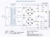
See attached pic, this is how PS should be wired:
You have two sets of secondaries on the transformer, colors don't mean anything to us without manufacturer's diagram. Identify secondary pairs by measure AC voltages; connect one set to pads marked AC2-AC2, the other set to AC1-AC1 (the orientation of wires is not critical as long as two pairs are sorted out properly)
Now measure voltages between V- and PG- and between V+ and PG+, it should be approx 2x 34V DC. If LED doesn't light up, it may be installed incorrectly and you need to reverse it.
All those measurements should be done without PS connected to the amp boards.
Forget about the bulb, it's good for testing complete amp, but you don't need it here yet.
See attached pic, this is how PS should be wired:
You have two sets of secondaries on the transformer, colors don't mean anything to us without manufacturer's diagram. Identify secondary pairs by measure AC voltages; connect one set to pads marked AC2-AC2, the other set to AC1-AC1 (the orientation of wires is not critical as long as two pairs are sorted out properly)
Now measure voltages between V- and PG- and between V+ and PG+, it should be approx 2x 34V DC. If LED doesn't light up, it may be installed incorrectly and you need to reverse it.
All those measurements should be done without PS connected to the amp boards.
Attachments
Last edited:
the purpose of the bulb tester is to prevent damage if any of the wiring is wrong and causes excessive power demand.
It is best used right from the start rather at the end of the building sequence.
It is best used right from the start rather at the end of the building sequence.
Well, I know that. But you can't make an error wiring a simple PS circuit, and I'm not completely sure if he did wire the bulb tester correctly, are you?
Ok guys please dont start fighting 🙂
My bulb tester is a monitor lead, cut in half.. Neutral and earth into block connector and the live in and out of bulb.
Its frustrating, but its my error somewhere. I'm sure it will be sorted soon.
My bulb tester is a monitor lead, cut in half.. Neutral and earth into block connector and the live in and out of bulb.
Its frustrating, but its my error somewhere. I'm sure it will be sorted soon.
if you are getting a spark trying to measure between -V and -PG, something is wrong. The bulb is lighting up because lots of current is being drawn - your multimeter will not do this!
Sweet just tried lefthand side amplifier and I'm getting 29.3v DC at the board... More impotantly No flashing lights or frazzling sounds.
On with testing righthand side and see if I'm as lucky. If so I will solder the rest together n break out the CD player and test outputs.
On with testing righthand side and see if I'm as lucky. If so I will solder the rest together n break out the CD player and test outputs.
Woo hoo... working all the way to speakers..... I'm a happy man!
Thanks Peter for a great kit and the oppertunity to have a go.
Thanks to all who helped with advice along the way... I'm off to listen to some AC/DC... See ya all soon!
Thanks Peter for a great kit and the oppertunity to have a go.
Thanks to all who helped with advice along the way... I'm off to listen to some AC/DC... See ya all soon!
Good stuff 🙂 With no signal in you shouldn't have anything hot either... the chips should not be hot, perhaps slightly warm.
BTW, where did you get the case you used, and how much did it cost?
BTW, where did you get the case you used, and how much did it cost?
Now sit back and enjoy, happy with the sound?
I went from being amazed it made sound, to amazed at the sound it made with my first chipamp.
John
I went from being amazed it made sound, to amazed at the sound it made with my first chipamp.
John
Ah I suspected it was a Modu case.. nice to know what the price is though from an actual purchase 🙂
I must say the case for its price is wicked.. It is one of the cheaper models, but the 10mm front panel makes it look nice.
As for the sound... Got my 3 year old grandson, yes grandson.. in the room next door asleep. Very inconsiderate of the little bugga eh.
Let you know the sound side tomoro.
Thanks again for help n advice.
As for the sound... Got my 3 year old grandson, yes grandson.. in the room next door asleep. Very inconsiderate of the little bugga eh.
Let you know the sound side tomoro.
Thanks again for help n advice.
Maybe mutitester
The multi meter will do this if it is set to mesure current . It was mentioned earlier in the thread about sparks when taking a mesurement.
Regards Ian
if you are getting a spark trying to measure between -V and -PG, something is wrong. The bulb is lighting up because lots of current is being drawn - your multimeter will not do this!
The multi meter will do this if it is set to mesure current . It was mentioned earlier in the thread about sparks when taking a mesurement.
Regards Ian
- Status
- Not open for further replies.
- Home
- More Vendors...
- Audio Sector
- LM4870 Noob mess up