I have a situation that i'm trying to resolve.. I messed up the diodes on my rectifiers by only half reading the intructions.. Anyway they went in back to front.
Peter said that it is possible to reverse polarity and use it as normal... However I have already tried to remove the first 8 from one rectifier with little success. I ended up snapping the pins off a few MUR's.
My question is.. Would it be possible to use the one rectifier I have with diodes in wrong way, to power both amp modules.
This is my first project and I have only myself to blame for errors, but I would like to know if I can make it work.... More chance of the wife letting me do project 2 😉.
Yes, you can use one rectifier board to power both amp modules; with a single transformer that's what I actually recommend.
Before you connect anything, check for proper voltages with a meter.
Before you connect anything, check for proper voltages with a meter.
Is the goal to remove and re-install the diodes in the correct orientation or are you just interested in not damaging the PCB? The clearance of the leads into the holes has a big effect on how successful you will be extracting the parts without damaging them or the board. Personally, I would cut the leads off the diodes and unsolder / extract the pins and then install new diodes. I know it's a pain getting more parts but getting new boards is usually much worse.
The (un)soldering tool has a big impact of how you might proceed. A cheapy not temperature controlled iron is most likely to damage the board and have insufficient heat to get the holes cleared. A decent temperature controlled iron (and not some piece of junk with a dial and a readout) improves your odds. A premo iron like a Metcal makes it almost easy - certainly for me. Still, if the hole / wire clearance is very small it _will_ be difficult and the best bet is to just clip them out and use new ones.
G²
I have both Amp sections completed. Gonna be after xmas before I get transformer so no more rushing!
Couple of questions I would like to ask...
Do I need to fill the zobel spaces with anything or does amp work without putting anything there?
Where do I connect my volume control?
I have got input and output sockets, would I be better testing before fitting these or wont it make a difference?
I know you guys can knock these kits together in no time, but its my first time with a soldering iron, let alone a kit like this.
Zobel is optional and I usually don't recommend it.
The volume control is connected to amp's input, see this for more details: http://www.diyaudio.com/forums/audi...-kit-building-instructions-3.html#post1516297
I guess it's actually easier to check the amp with input/output connectors attached.
The volume control is connected to amp's input, see this for more details: http://www.diyaudio.com/forums/audi...-kit-building-instructions-3.html#post1516297
I guess it's actually easier to check the amp with input/output connectors attached.
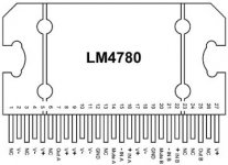
Next bit... I understand that the LM4780 cannot be grounded to chassis. I guess this also means my heatsink cannot touch the ground too.
If I build a wood case do I just run a ground from my mains earth wire to a point and connect other grounds.
I was gonna go with aluminium case, but I think wood will be better for first go.
If I build a wood case do I just run a ground from my mains earth wire to a point and connect other grounds.
I was gonna go with aluminium case, but I think wood will be better for first go.
It's best to isolate LM4780 chip from metal heatsink and simply ground the heatsink.
All exposed metal parts should be connected to Earth ground. I separate audio grounds from Earth ground with 10R resistor.
All exposed metal parts should be connected to Earth ground. I separate audio grounds from Earth ground with 10R resistor.
ahh so is the strip of film to isolate chip from heatsink... lol I know you hate me but I promise no questions when I do MkII.
Still got transformer to get yet, so i'm sure i'll be back for more...sorry!
Still got transformer to get yet, so i'm sure i'll be back for more...sorry!
Do i have to solder every pin on the chip.. At the moment I have just soldered the ends to hold it in place. It is secure, but I'm not sure if it will connect without solder.
I am thinking of using the box AB15 here.. Aluminium Boxes : Instrument Cases : Maplin for the case..
If i fasten lm chip to the base would this be enough to act as heatsink or will it need more?
I intend to put feet on so it will have a gap to breath.
If i fasten lm chip to the base would this be enough to act as heatsink or will it need more?
I intend to put feet on so it will have a gap to breath.
You guys must have some eyesight... I did 5 pins on the chip and my eyes went blurry... Try another 5 later I guess. I tried a magnifier but that made me go blurry without doing anything lol.
You guys must have some eyesight... I did 5 pins on the chip and my eyes went blurry... Try another 5 later I guess. I tried a magnifier but that made me go blurry without doing anything lol.
Sounds like it's time for a trip to the eye doctor for you!
- Status
- Not open for further replies.
- Home
- More Vendors...
- Audio Sector
- LM4870 Noob mess up