Re: So nice!
Robert,
The mute isn't implemented. The resistor is hardwired there to give provide .5mA of current to the mute pin, which keeps the chip out of the mute mode. I see no real reason for this implementation for a mute, but it could easily be implemented by modifying the layout to allow you to make an open circuit to the mute pin.
--
Brian
RFScheer said:Brian,
You are a true arteest.
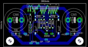
Regarding the muting situation, you provided a spot for attaching a surface mount resistor between v- and pins 14 and 20 but there isn't a solder mask shape on the sm pads. Also, how would you actually use the mute? Don't you need an external pad to connect a toggle switch to?
-Robert
Robert,
The mute isn't implemented. The resistor is hardwired there to give provide .5mA of current to the mute pin, which keeps the chip out of the mute mode. I see no real reason for this implementation for a mute, but it could easily be implemented by modifying the layout to allow you to make an open circuit to the mute pin.
--
Brian
Does the implementation of the mute switch in some way affect the quality of the sound or have some other adverse effect on the amplifier?
Jim
Jim
Mute
Is anyone planning to experiment with muting as a precision attenuation technique?
Maybe a stupid idea, but putting the attenuator in place of the mute resistor would a) remove it from the signal path and b) allow a cheaper attenuator that is easy to make pop-free.
Seems so obvious someone must have already done this. Bad results?
-Robert
From reading the spec sheets, I gather the mute is either (softfade) on or off, not an analogue attenuation
This looks good to me. Let's give people another 48hrs to debate any further issues and then finalize it for the group order. I'll get to work on a PayPal page for people interested.
Sound good?
Sound good?
Mute
If people are going to add an input stage to their boards, the turning on and off of the amp could cause spikes from the input stage to flow through the GC. Thus, the mute function could be used to avoid these spikes.
I had an issue with this on my Buffered Inverting Gainclone before I fine tuned the capacitance and voltage regulators on the input stage. Mute came in handy.
Kevin Haskins said:This looks good to me. Let's give people another 48hrs to debate any further issues and then finalize it for the group order. I'll get to work on a PayPal page for people interested.
Sound good?
Since this layout was initiated by me and later finalized by Brian, the artwork actually belongs to both of us. I will be pursuing this design in my commercial version of more powerfull amp, so it's seem only natural, that I want to have some control over this artwork. If this design goes into group buy process, it will be handled either by Brian or me.
Which doesn't mean that different layout cannot be proposed for group buy purpose. It just happens that I like this particualr one quite a lot😉
I'm sorry... I thought the entire purpose of this thread had been to come up with a design for the group buy and I'd offered to handle the legwork. If that is going to be a problem I don't have any problem with either Brian or you handling the group order with the use of the final design or using a different one for the group purchase.
I'm easy... whatever works for you guys.
I'm easy... whatever works for you guys.
Is this going to be the end of this thread?
It sounds like someone has just "crossed the imaginary line drawn in the sand" and "muddied the waters".
Hey, Peter and Brian, can you get together and let us know your intentions. I think most of us would have "assumed" a group buy was at the end of all this.
BTW, I appreciate both your efforts in the DIY community and I don't want to sound like someone who is expecting handouts from people like yourselves who are always going that extra mile (or two) for us.
Thanks
I meant, if you guys decide that those boards are good enough for a group buy, then the group buy will happen. I don't mind it at all.😉
Re: Is this going to be the end of this thread?
There will definately be a group buy for this, and it will most likely be carried out in a very similar manner to the current LM3875 group order, with pcbs, basic kits, and premium kits offered.
I will be organizing the order, and Peter will help out, handling the international and canadian orders.
As for the pcbs, I am looking them with 4 oz copper, since there will be more current on the power supply lines. I am also going to include 2 power supply boards, and 2 amplifier pcbs with each pcb set, since monoblocks are quite an attractive option for this setup. I am also considering getting these boards colored black, to set them apart from the red LM3875 pcbs.
Expect details to be finalized in the near future, after I work with Peter to determine what would work out best for the kits. I want to make the prices as low as possible.
A portion of the board/kit sales will again be donated to diyaudio, as with the last offering.
--
Brian
grege said:It sounds like someone has just "crossed the imaginary line drawn in the sand" and "muddied the waters".
Hey, Peter and Brian, can you get together and let us know your intentions. I think most of us would have "assumed" a group buy was at the end of all this.
BTW, I appreciate both your efforts in the DIY community and I don't want to sound like someone who is expecting handouts from people like yourselves who are always going that extra mile (or two) for us.
Thanks
There will definately be a group buy for this, and it will most likely be carried out in a very similar manner to the current LM3875 group order, with pcbs, basic kits, and premium kits offered.
I will be organizing the order, and Peter will help out, handling the international and canadian orders.
As for the pcbs, I am looking them with 4 oz copper, since there will be more current on the power supply lines. I am also going to include 2 power supply boards, and 2 amplifier pcbs with each pcb set, since monoblocks are quite an attractive option for this setup. I am also considering getting these boards colored black, to set them apart from the red LM3875 pcbs.
Expect details to be finalized in the near future, after I work with Peter to determine what would work out best for the kits. I want to make the prices as low as possible.
A portion of the board/kit sales will again be donated to diyaudio, as with the last offering.
--
Brian
Can you explain in detail how you can bridge the boards for more power? Will you need 4 amp boards and 4 power boards for this (and possibly 4 TFs)?
Jamh said:Can you explain in detail how you can bridge the boards for more power? Will you need 4 amp boards and 4 power boards for this (and possibly 4 TFs)?
For the LM4780, there are 2 channels paralled per channel. A bridging board would be needed for paralleling 2 amplifier board. A single power supply board could be used for the 2 channels.
A bridging solution is being investigated to go along with this.
I am getting prototypes made for these pcbs soon, as the design is a bit more complex, and I would like to verify the design before getting a large batch of boards made.
--
Brian
Thanks Brian! I was just curious how high you can go in power. Using both channels in each chip gets you perhaps 40 to 50W. Can bridging bring it to the 100W level?
Jamh said:Thanks Brian! I was just curious how high you can go in power. Using both channels in each chip gets you perhaps 40 to 50W. Can bridging bring it to the 100W level?
It depends on the load that you are running. Remember that when you bridge an amplifier, each amplifier sees half the impedence of the load. This means that if you are driving an 8 ohm load, each side will see 4 ohms. If you are running 34v rails, you will get around 70w rms power (based on the 35w rms that I measured on my single channel gainclone with 34v rails into an 4 ohm load). Be careful bridging with a 4 ohm load, since each side would see a 2 ohm load.
When you parallel 2 channels together, each channel sees twice the load impedence. If you had a 4 ohm pair of speakers, and paralled the amplifiers, you would get about 60w total on 34v rails. (based on the 30w rms that I measured on my single channel gainclone with 34v rails into an 8 ohm load). If you increase the power supply rails to 40v or so, you can get more power out of it.
If you look at the National BPA200 appnote, they show a bridged-parallel amplifier using 6 channels, and putting out around 200w into an 8 ohm load. (more with a 4 ohm load)
The LM4780 pcb that is currently looking to become a group order is essentially 2 parallel LM3875 channels, so if you bridge them, it will be much tolerant of low impedence loads.
I am in the process of building a bridgeclone, which uses 6 of my LM3875 pcbs (1 power supply board per channel), and I expect it to put out 200w+ per channel. I am just using an output resistor on the output of the 3 parallel channels, and the bridging will be done with the DRV134. I haven't had any free time to work on it lately, due to the mailing out of the LM3875 kits, but I will try to make it into lab again soon.
--
Brian
Cool. Of course my little jordan drivers would panic! They're perfectly happy with a single LM3875. I think your six channel affair would be great. You can either use it for home theatre or to power two three-way speakers without a network (maybe an active crossover before the power amp). Ideally, you can use the LM3875 for the highs and mids and the more powerful 4780 for the bass. I'd love to hear something like that.
moamps said:.....single layer design with a little pins rearrangement ...
It is pretty nice design. However, it doesn't look like STD BG caps will fit there. Also, removing the IC pins is not what people really want.
Jamh said:Cool. Of course my little jordan drivers would panic! They're perfectly happy with a single LM3875. I think your six channel affair would be great. You can either use it for home theatre or to power two three-way speakers without a network (maybe an active crossover before the power amp). Ideally, you can use the LM3875 for the highs and mids and the more powerful 4780 for the bass. I'd love to hear something like that.
This is exactly my plan, using the 4780 for the low end, or even a bridged 4780 for a really inefficient low end (with equilization)
--
Brian
I am going to try hard to get some prototype boards ordered at the end of this week for the LM4780, and if everything goes well, we could have a group order starting in a couple of weeks for this.
--
Brian
--
Brian
- Status
- Not open for further replies.
- Home
- Amplifiers
- Chip Amps
- LM4780 pcb layout and others