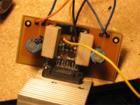
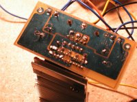
CrisTUFR said:Here you go! I optimized the images for quick downloading, and hence they're only 320x240 for the forum right now. They give the general idea of the quality of the build, which is generally not all that bad.
Now if only I could figure out how to make them red... 😉
Board looks good!
As for the red, I am thinking about making the LM4780 boards black. Do you think that red is better than black? A different color (yellow maybe) could be used for the silkscreen.
--
Brian
As for the red, I am thinking about making the LM4780 boards black. Do you think that red is better than black? A different color (yellow maybe) could be used for the silkscreen.
I don't know Brian, I hear that "Black is the new Red"! 😉
I figure that you're probably better off with black, just to distinguish them from the 3875 boards... But that's just my worthless opinion! 🙂
Now I have to figure out how to put these bad-boys into a nice enclosure, and move on to doing some funky stuff with some TangBand 871's to complete my entire PC audio setup!!! 😀
Cheers,
Chris
Well, with a prototype made with the board layout, I am considering organizing the order based on the current layout.
As for pricing, it looks like 1 pcb set would cost $20, and include:
- 2 power supply boards
- 2 amplifier boards
- 1 bridging board (DRV134)
This price would be for 4 oz copper (for the extra current handling), and the boards would be put together with scoring, as with my current LM4780 boards. (boards to either be red or black)
The amplifier pcb would be a single LM4780 chip hardwired in paralled configuration.
One pcb set would allow for these configurations:
- 2 channel amplifier (one amplifier pcb per channel) with a single or dual power supplies. (dual monoblock setup possible with one pcb set)
- bridged setup producing 150-200w for one channel
Remember that the LM4780 is hardwired in parallel mode, so one chip = 1 channel.
The non-bridged board should put out around 50-100w, depending on the power supply voltages and the load driven.
Kits will also be offered, and pricing will be announced soon. Pricing should be just a bit more than the current LM3875 group order.
I modified the Wiki for a new list to see the interest out there. If the interest is fairly substantial (100+ pcbs being the target to get the price), I will go through with the order, and offer kits. Please sign-up again here:
http://www.diyaudio.com/wiki/index.php?page=LM4780+Eval+PCB+Group+Order
Please indicate your initial interest. This will allow for me to determine the kit pricing, and the whether there is enough interest for me to put time into this.
Drop me an e-mail if you have any questions. PCB set pictures will be posted soon.
--
Brian
For the group order that I am organizing, please follow through in the new thread that I created for it:
http://www.diyaudio.com/forums/showthread.php?s=&threadid=33863
--
Brian
http://www.diyaudio.com/forums/showthread.php?s=&threadid=33863
--
Brian
Terrific thread
This discussion has been most educational for me. Great work, you guys. Thank you.
Being a hobbyist-level constructor, I was fascinated by the discussion as you balanced all the operating requirements against each other. I found the grounding discussions particularly interesting - never knew there was so much to it!
Anyhow, I can see that there is definitely a logic to it, but also a good deal of intuition and aesthetic judgement. Designing truly is an art form, and Peter and Brian sure are great artists.
The boards look fantastic!
I hope more discussions like this can take place on the forum, here. Although I can only grasp much of the banter at a very elementary and conceptual level, I did learn a lot.
Great job!
KT
confused... BrianGT and Peter's board
This thread no doubt came to a logical conclusion but i got confused.This is wrt to final pcb.zip posted by BrianGt. I saw the layout and tried to compare it with some scehmatics in the data sheet and was surprised to find that it doesnt match with any version of the amp.
Can some one please give more details.I also observed that there 9 resistors and two caps. It would be very nice if someone could post a schematic. I am a newbie and I prefer looking at schematics before starting with the board. Bill of material along with schematics will also help. I am sure most of you guys would have already incorporated this design.Also how this amp sounds will really motivate me in finishing the proj this weekend itself 🙂
Thanks.
Brian: What is status?
Brian what is the status of 4780 PCB project?
I know you have been very busy, but is the project dead or not?
Thanks,
Sheldon
Brian what is the status of 4780 PCB project?
I know you have been very busy, but is the project dead or not?
Thanks,
Sheldon
mm after read this threat dont understand what means "P2P designs" 😀
can someone explain me please?
can someone explain me please?
Hey, I know this one...
"Point to point" Soldering the compentents to each other without a circuit board. This can be seen on a lot of Gainclones because of the small number of parts.
By the by. Congratulations on the basketball & soccer golds in Athens! Way to go Argentina!
Cheers,
Bret Morrow
samsagaz said:mm after read this threat dont understand what means "P2P designs" 😀
can someone explain me please?
"Point to point" Soldering the compentents to each other without a circuit board. This can be seen on a lot of Gainclones because of the small number of parts.
By the by. Congratulations on the basketball & soccer golds in Athens! Way to go Argentina!
Cheers,
Bret Morrow
Example of P2P project
Take a look at the following web site for pictures of lots of P2P projects
http://users.verat.net/~pedjarogic/audio/gainclone/gainclone_pics.htm
Cheers,
Bret Morrow
Take a look at the following web site for pictures of lots of P2P projects
http://users.verat.net/~pedjarogic/audio/gainclone/gainclone_pics.htm
Cheers,
Bret Morrow
amazing pcbs dudes..... someone know some tutorial abt how design it?
im using proteus.... maybe using another soft will be easy to create the design PCBs?
im using proteus.... maybe using another soft will be easy to create the design PCBs?
someone have the link schematic of the lm4780 proyect from BrainGT? i searched it but cant found it 🙁
since the wiki page for this groupbuy says that it is not in use anymore, does anybody know if LM4780-kits can be ordered at the moment, or is it finished?
I want to by one, and i do not know if they can be ordered.
I want to by one, and i do not know if they can be ordered.
samsagaz said:someone have the link schematic of the lm4780 proyect from BrainGT? i searched it but cant found it 🙁
wim said:since the wiki page for this groupbuy says that it is not in use anymore, does anybody know if LM4780-kits can be ordered at the moment, or is it finished?
I want to by one, and i do not know if they can be ordered.
http://www.chipamp.com/
- Status
- Not open for further replies.
- Home
- Amplifiers
- Chip Amps
- LM4780 pcb layout and others