moamps said:..single layer design ....PDF
Can you post the Eagle files also?
moamps said:..single layer design ....PDF
What is the seemingly unconnected trace for coming off the signal gnd and terminating under RB2?
--
Brian
BrianGT said:
What is the seemingly unconnected trace for coming off the signal gnd and terminating under RB2?
Here is a picture of the trace that I am referring to from the pdf.
--
Brian
Attachments

What are their call letters?
are they fc ? bk?
Thanks
Jean-PIerre
Peter Daniel said:I also think that those blue Panasonics from DigiKey could be used here. They are pretty popular with Pass Labs (and not expensive).
are they fc ? bk?
Thanks
Jean-PIerre
BrianGT said:Here is a picture of the trace that I am referring to from the pdf.
Hi,
This is the ground shield between +in and output (to prevent high frequency instability).
Regards
Guard trace?BrianGT said:
Here is a picture of the trace that I am referring to from the pdf.
--
Brian
EDIT: Too slow, but at least correct. 😉
tiroth said:
Guard trace?
Hi,
Yes, if +in is very close to output.
Also, here is Eagle file for Alcaid.
Regards
Attachments
Hey moamps,
How did you get the nice white "holes" to show up in the pads for the parts using Eagle? I can never get that to work, and have to suffer at the mercy of my drill "skating" around my pads... 🙁
Thanks,
Chris
How did you get the nice white "holes" to show up in the pads for the parts using Eagle? I can never get that to work, and have to suffer at the mercy of my drill "skating" around my pads... 🙁
Thanks,
Chris
moamps said:
Hi,
Yes, if +in is very close to output.
Also, here is Eagle file for Alcaid.
Regards
Do you have a cracked version of Eagle?
Wasn't able to open it. 🙁
I'd be interested in the schematic also if there is any.
Alcaid said:Do you have a cracked version of Eagle?
Wasn't able to open it.
Hi,
this is one older education version (4.01) I got from one friend.
I don't now where is problem.
Maybe, because I designed chip pining myself in 4 rows . 🙁
Regards
Hi, if other people want to see the board file, they will need a copy of the library file you created with the LM4780 chip in it to be able to open the board file. If you posted a copy of this, people would need to move the library file into the lbr folder in the eagle directory on their hard drive to view things properly.
By the way you uploaded the .b#1 file and not the .brd file. Then it's not the newest version. Don't you have a schematic?
To provide an update on my progress, I've managed to etch the BrianGT design on a double-sided presensitized board. So far everything looks like it lined up okay.
Tonight I'll drill away (carefully!) and hopefully get something assembled. Out of the 8 (!) boards that I produced (I had a 6x6 board -- all my local shop had) only 4 survived. 🙁
I will let you all know how well it works when done fully DIY at home. So far, the drilling doesn't look too clean on the "other side" and hopefully it doesn't affect the soldering of the board.
I'll keep you all posted.
Cheers,
Chris
I just print bottom side with holes in PDF.CrisTUFR said:How did you get the nice white "holes" to show up in the pads for the parts using Eagle?
I haven't schematic. I don't use autorouter. I use Eagle just like graphic tools. Schematic is similar to Brian's few page ago.Alcaid said:By the way you uploaded the .b#1 file and not the .brd file. Then it's not the newest version. Don't you have a schematic?
Regards
moamps said:
I just print bottom side with holes in PDF.
Well whenever I create something in Eagle, and route the traces manually, often times the traces overlap the holes. I guess since you're not using a schematic, you probably draw the traces to simply "touch" the edges of the pads, and not run over them, correct?
I guess I'll never figure out how to get the holes to stay. 😛
Chris
I've built up one of the boards that came out from the etching process. It was a bit of a pain to drill (first time with the dremel press...) but it turned out okay.
I don't have any of the fancy-schmancy resistors that you guys suggest for the design, and I deviated slightly on the values of some of them (20 vs 22k all around). I did use 1% resistors for all of them, so it ain't all *that* bad...
Also, I used my 5W sandbars on the output for this. Placement was a pain all around, and I used a scrap SMT resistor I pulled off of something a while ago.
I just said "screw it" and powered it up after assembly (since I trusted Brian and all the diyaudio folk's design, and didn't make any fatal mistakes while soldering) and to my amazement it seemed to work okay. Unfortunately, I have a constant buzz which I also noticed on the last few p2p wirings I've done that have not included any filtering caps other than the power decoupling caps, and turning the 50k pot I use to the min and max produces static.
I think that there are some other issues with my setup that I have to resolve before going further (like the power supply which consists of a surplus rectifier bridge, some 200V 470uf caps about 1ft away, and 100uf 50V caps as decoupling caps on the PCB). I'm sure that will give you an idea of how crappy things likely are.
On the scope, I noticed some interesting tidbits that you guys might want to hear about (I don't know if they're my issues, or the design...you guys talk amongst yourselves). Between the -ve voltage line and the ground plane I notice that there's a lot of signal crosstalk from the audio. Also, I noticed that my caps must not be supplying enough smoothing since there's the textbook "caps after rectifier" saw wave showing up mixed with the audio signal. Does this make sense? Do you think the fuzz/buzz I'm hearing has to do with the power supply rejection kicking in?
Anyway, if you guys want measurements of certain areas or whatever, just give me a shout and I'll probe away for you. I'm looking forward to hear what you guys suggest I try.
(As an aside, has anyone else got one of these bad-boys built?)
Cheers,
Chris
After a lot of trial and error (mixed with working in a rush) I figured out the source of all the badness.
I was a bit silly in my interconnects, and tried to integrate the PCB into an existing configuration (that had its own ground star). Obviously, this is a suboptimal grounding configuration, because BrianGT's board takes care of grounding for you.
Today at lunch time, I re-wired everything "properly" with two of the populated boards and voila! It sounded perfectly fantabulous! I am running it with a regulated supply I built using my own PCB design (originally based on Pedja's regulated schematic, but changed to work with my desired voltages) and it works awful well.
So if you guys had any doubts about whether or not the layout works, you can set them aside. It works quite well! 😉
Thanks for providing the artwork, Brian!
Cheers,
Chris
CrisTUFR said:After a lot of trial and error (mixed with working in a rush) I figured out the source of all the badness.
I was a bit silly in my interconnects, and tried to integrate the PCB into an existing configuration (that had its own ground star). Obviously, this is a suboptimal grounding configuration, because BrianGT's board takes care of grounding for you.
Today at lunch time, I re-wired everything "properly" with two of the populated boards and voila! It sounded perfectly fantabulous! I am running it with a regulated supply I built using my own PCB design (originally based on Pedja's regulated schematic, but changed to work with my desired voltages) and it works awful well.
So if you guys had any doubts about whether or not the layout works, you can set them aside. It works quite well! 😉
Thanks for providing the artwork, Brian!
Cheers,
Chris
Chris,
I am glad to hear that it works well for you! I will be ordering the prototype pcbs soon, and should be posting results with them in a week or so, then organize an order like last time.
Please post some pictures, as I am curious to see how it came out.
--
Brian
BrianGT said:
Please post some pictures, as I am curious to see how it came out.
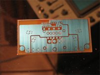
Here you go! I optimized the images for quick downloading, and hence they're only 320x240 for the forum right now. They give the general idea of the quality of the build, which is generally not all that bad.
Had everything gone perfectly for me during the developing/etching, I would have made 8 boards for about $15 CDN. Drilling would have been cleaner if there was no copper around the pads, but I'm not being picky about that... 😉
The error in etching was mainly my stupidity getting the better of me, and using a piece of glass that was smaller than the area of the board I was developing. The edge of the glass left a hard line shorting out half of the 4780 pins on two of the boards. Another two boards may have been accidentally exposed to some light while I was lining up for the double sided exposure, however they may still be useful, as only a part of the V- and V+ planes got faded.
Now if only I could figure out how to make them red... 😉
Below is the bare board without any drilling.
Cheers,
Chris
Attachments
- Status
- Not open for further replies.
- Home
- Amplifiers
- Chip Amps
- LM4780 pcb layout and others