Grounding - last shot
One more whimper from me on this topic.
Brian, your layout by connecting signal ground to the big ground plane is not like National's. They have a resistor called "RG" that appears to connect the star signal ground to the main ground but isn't it a jumper that can be left isolated if desired? Signal ground for their pcb comes from the rca input jack shields.
Furthermore, there is no advantage to providing the big ground plane on the pcb. It is just wasting space. You still expect to connect PG+, OG, CHG, PG- and SG wires to pads at the edge of the board. 5 wires.
Consider instead:
PG+ - connect this wire coming from ps card to a pad as close as possible to the neg terminal of V+ cap. That's about 1 square of resistance ~ 0.45mohm.
OG - connect this wire coming from + speaker jack to the star point on the ps card, not the amp card.
CHG - connect this wire from the chassis to the star point on the ps card, not the amp card.
PG- - connect this wire coming from the ps card to a pad as close as possible to the pos terminal of the V- cap.
SG - Disconnect the input jack shields from common SG. Provide a separate pad for them. Provide another pad for the new isolated SG. Experiment with connecting the 2 signal level grounds in ways not necessary to enumerate here.
As a result of the above, you can both improve ground induced noise on the inputs and collapse much of the space used by the common ground plane and somewhat shrink your pcb size.
-Robert
Re: Grounding - last shot
Interesting suggestions. I will take play around with the layout again and see what I can come up with. The board could definately be made smaller if I followed your suggestions.
As for the national layout, they do tie the signal ground together with the power supply ground, through a 2.7 ohm resistor called Rg. I am wondering if it would be good to copy this methodology, and a short jumper wire could also be tried in place of the resistor.
--
Brian
RFScheer said:One more whimper from me on this topic.
Brian, your layout by connecting signal ground to the big ground plane is not like National's. They have a resistor called "RG" that appears to connect the star signal ground to the main ground but isn't it a jumper that can be left isolated if desired? Signal ground for their pcb comes from the rca input jack shields.
Furthermore, there is no advantage to providing the big ground plane on the pcb. It is just wasting space. You still expect to connect PG+, OG, CHG, PG- and SG wires to pads at the edge of the board. 5 wires.
Consider instead:
PG+ - connect this wire coming from ps card to a pad as close as possible to the neg terminal of V+ cap. That's about 1 square of resistance ~ 0.45mohm.
OG - connect this wire coming from + speaker jack to the star point on the ps card, not the amp card.
CHG - connect this wire from the chassis to the star point on the ps card, not the amp card.
PG- - connect this wire coming from the ps card to a pad as close as possible to the pos terminal of the V- cap.
SG - Disconnect the input jack shields from common SG. Provide a separate pad for them. Provide another pad for the new isolated SG. Experiment with connecting the 2 signal level grounds in ways not necessary to enumerate here.
As a result of the above, you can both improve ground induced noise on the inputs and collapse much of the space used by the common ground plane and somewhat shrink your pcb size.
-Robert
Interesting suggestions. I will take play around with the layout again and see what I can come up with. The board could definately be made smaller if I followed your suggestions.
As for the national layout, they do tie the signal ground together with the power supply ground, through a 2.7 ohm resistor called Rg. I am wondering if it would be good to copy this methodology, and a short jumper wire could also be tried in place of the resistor.
--
Brian
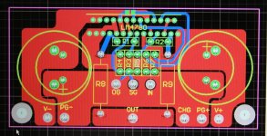
BrianBrianGT said:Here is an image of my revised layout, making it a bit deeper (0.05" deeper), and moving the output GND pad down more. I positioned the input terminals closer to the middle to keep the GND trace as thick as possible.
Any comments?
 but I would go even further, try to isolate the "sense" even more. Move the speakerground up a but and try to keep away the PS currents even more. You could even make the trace smaller or narrower, just around the pad.
Re: Grounding - last shot
Those are not big ground planes. When you look at amp's board thay are rather small.
I would still leave OG and CHG on the amp's board. You don't have to use those terminals and they are not in way of anything on a board. SG is just signal ground. It comes from RCA ground lug. It has nothing to do with a shield. You are not using shielded wires inside the amp.
The board is so small, that I don't see any advantage in connecting PS wires anything closer to caps than they are already. It is mostly for convenience and I wouldn't see how this affects performance. You can always solder them directly to cap's pins, underneath.
This board should be practical and easy to implement, and furhter modifications shouldn't be a problem.
RFScheer said:One more whimper from me on this topic.
Furthermore, there is no advantage to providing the big ground plane on the pcb. It is just wasting space. You still expect to connect PG+, OG, CHG, PG- and SG wires to pads at the edge of the board. 5 wires.
Consider instead:
PG+ - connect this wire coming from ps card to a pad as close as possible to the neg terminal of V+ cap. That's about 1 square of resistance ~ 0.45mohm.
OG - connect this wire coming from + speaker jack to the star point on the ps card, not the amp card.
CHG - connect this wire from the chassis to the star point on the ps card, not the amp card.
PG- - connect this wire coming from the ps card to a pad as close as possible to the pos terminal of the V- cap.
SG - Disconnect the input jack shields from common SG. Provide a separate pad for them. Provide another pad for the new isolated SG. Experiment with connecting the 2 signal level grounds in ways not necessary to enumerate here.
As a result of the above, you can both improve ground induced noise on the inputs and collapse much of the space used by the common ground plane and somewhat shrink your pcb size.
-Robert
Those are not big ground planes. When you look at amp's board thay are rather small.
I would still leave OG and CHG on the amp's board. You don't have to use those terminals and they are not in way of anything on a board. SG is just signal ground. It comes from RCA ground lug. It has nothing to do with a shield. You are not using shielded wires inside the amp.
The board is so small, that I don't see any advantage in connecting PS wires anything closer to caps than they are already. It is mostly for convenience and I wouldn't see how this affects performance. You can always solder them directly to cap's pins, underneath.
This board should be practical and easy to implement, and furhter modifications shouldn't be a problem.
Thanks for response
My only goal in this sub-thread about grounding has been to remove the large ground return currents from the amp board entirely so they have no chance of injecting a signal into the input. After considering ALW's and Peranders' objections to the grounding early on, I started thinking and calculating and now understand more about this.
Everyone involved with these board layouts should be certain they thoroughly understand how the grounding works. From some of the discussion, I'm afraid not everyone does. I can understand why you would want to preserve as much of the layout from the previous LM3875 project as possible. Hey - those boards work, right? Maybe I should have said this earlier, but I had to fool around with the grounding to get my BrianGT amp to be quiet (low volume 120Hz buzz) and to stop heating up on idle. Unfortunately for this discussion, my alterations were made without today's understanding and so I need to go back and do some improvements (can't do till next week). How many people out there have mentioned ground noise, oscillating and heating up?
I don't care if the 4780 board is twice as big or half as small, it's not that important to me. By pointing out these changes would save area, that was just to show there was more benefit than just removing problems from the signal ground.
Peter, here's the problem with leaving OG and CHG on the amp board. True, you can leave them disconnected, and instead connect the wires to the ps board. But the groundplane is still there and this connects the two power capacitor ground terminals to each other (bad). We realize that during most of the power supply rectification cycle, the FULL CURRENT driving into the speaker must come from one of the capacitors at any given moment, not from the transformer. The current coming back from the speaker comes into the OG terminal then across the groundplane and directly back to the capacitor ground terminal. The big problem is when the current is flowing from OG on the left side of the card back to the capacitor on the right. This current drops many mv's across the resistance of the groundplane and that directly raises the voltage of the SG (if it is connected to the main groundplane). This is 120Hz NOISE and it's guaranteed.
Edit added after orig post - Almost forgot to mention. If you omit connecting speaker ground wire to OG, you still have the problem and it actually gets worse. The capacitor that was sourcing the current to the speaker needs to collect it back through it's ground terminal from somewhere and that will come from the other capacitor so the current flowing across the card will now occur on every significant output either positive or negative.
Peter, I greatly respect the amazing work and leadership you've provided around here. I'm new, so I'll work hard to make sure you don't continue thinking I'm an idiot. Why would I think there are shielded connections inside the amp? I'm trying to point out that the ground terminals of the RCA lugs will bring unwanted ground current into the amp groundplane from the upstream equipment through the cable shields. If the ground potential difference between pieces of equipment is more than a few mv apart, you will have audible noise. The National layout has that RG resistor (Brian says is 2.5 ohms) that is indicated to connect SG to the main ground on the amp board. Why is it there? It may be the best use of it is to remove it and allow the SG to be defined by any of several better means.
Sorry for ranting. Not my style. I just don't like being dismissed without consideration.
-Robert
My only goal in this sub-thread about grounding has been to remove the large ground return currents from the amp board entirely so they have no chance of injecting a signal into the input. After considering ALW's and Peranders' objections to the grounding early on, I started thinking and calculating and now understand more about this.
Everyone involved with these board layouts should be certain they thoroughly understand how the grounding works. From some of the discussion, I'm afraid not everyone does. I can understand why you would want to preserve as much of the layout from the previous LM3875 project as possible. Hey - those boards work, right? Maybe I should have said this earlier, but I had to fool around with the grounding to get my BrianGT amp to be quiet (low volume 120Hz buzz) and to stop heating up on idle. Unfortunately for this discussion, my alterations were made without today's understanding and so I need to go back and do some improvements (can't do till next week). How many people out there have mentioned ground noise, oscillating and heating up?
I don't care if the 4780 board is twice as big or half as small, it's not that important to me. By pointing out these changes would save area, that was just to show there was more benefit than just removing problems from the signal ground.
Peter, here's the problem with leaving OG and CHG on the amp board. True, you can leave them disconnected, and instead connect the wires to the ps board. But the groundplane is still there and this connects the two power capacitor ground terminals to each other (bad). We realize that during most of the power supply rectification cycle, the FULL CURRENT driving into the speaker must come from one of the capacitors at any given moment, not from the transformer. The current coming back from the speaker comes into the OG terminal then across the groundplane and directly back to the capacitor ground terminal. The big problem is when the current is flowing from OG on the left side of the card back to the capacitor on the right. This current drops many mv's across the resistance of the groundplane and that directly raises the voltage of the SG (if it is connected to the main groundplane). This is 120Hz NOISE and it's guaranteed.
Edit added after orig post - Almost forgot to mention. If you omit connecting speaker ground wire to OG, you still have the problem and it actually gets worse. The capacitor that was sourcing the current to the speaker needs to collect it back through it's ground terminal from somewhere and that will come from the other capacitor so the current flowing across the card will now occur on every significant output either positive or negative.
Peter objected - SG is just signal ground. It comes from RCA ground lug. It has nothing to do with a shield. You are not using shielded wires inside the amp.
Peter, I greatly respect the amazing work and leadership you've provided around here. I'm new, so I'll work hard to make sure you don't continue thinking I'm an idiot. Why would I think there are shielded connections inside the amp? I'm trying to point out that the ground terminals of the RCA lugs will bring unwanted ground current into the amp groundplane from the upstream equipment through the cable shields. If the ground potential difference between pieces of equipment is more than a few mv apart, you will have audible noise. The National layout has that RG resistor (Brian says is 2.5 ohms) that is indicated to connect SG to the main ground on the amp board. Why is it there? It may be the best use of it is to remove it and allow the SG to be defined by any of several better means.
Sorry for ranting. Not my style. I just don't like being dismissed without consideration.
-Robert
Re: Thanks for response
I don't see how the amp can work without RCA ground terminal connected to the SG. You might want to use resistor, however, I never needed it. Why is it there? To make the board fool proof. I'm omiting much more, other important parts, than just the ground resistor. My board is not designed to be full proofed. It's designed for best sonic performance (and convenience).
If you don't connect 2 ground pins of caps on the board, where would you connect them when you use outboard PS? At the rectifiers? The ground path becomes much longer. Is it better?
Didn't you noticed that National also connects both grounds on the board? I don't really follow what you are trying to point out?
You can always connect both grounds at rectifier's board and run one ground wire to amp's board, if you choose.
RFScheer said:I'm trying to point out that the ground terminals of the RCA lugs will bring unwanted ground current into the amp groundplane from the upstream equipment through the cable shields. If the ground potential difference between pieces of equipment is more than a few mv apart, you will have audible noise. The National layout has that RG resistor (Brian says is 2.5 ohms) that is indicated to connect SG to the main ground on the amp board. Why is it there? It may be the best use of it is to remove it and allow the SG to be defined by any of several better means.
I don't see how the amp can work without RCA ground terminal connected to the SG. You might want to use resistor, however, I never needed it. Why is it there? To make the board fool proof. I'm omiting much more, other important parts, than just the ground resistor. My board is not designed to be full proofed. It's designed for best sonic performance (and convenience).
If you don't connect 2 ground pins of caps on the board, where would you connect them when you use outboard PS? At the rectifiers? The ground path becomes much longer. Is it better?
Didn't you noticed that National also connects both grounds on the board? I don't really follow what you are trying to point out?
You can always connect both grounds at rectifier's board and run one ground wire to amp's board, if you choose.
1%
That's my estimate for the ratio of ground noise to input signal voltage in my system with nearly 4ohm speakers. 8 ohm would have half the problem. I believe noise at the 1% level or even 0.1% level is worth dealing with, even if it's hard to hear.
-Robert
That's my estimate for the ratio of ground noise to input signal voltage in my system with nearly 4ohm speakers. 8 ohm would have half the problem. I believe noise at the 1% level or even 0.1% level is worth dealing with, even if it's hard to hear.
-Robert
Isolate SG groundplane
Peter,
That's not what I was proposing. The SG plane on the amp card (that connects the bottom of the resistors) should be isolated from the main ground plane on the amp card so the voltage of SG doesn't move up and down with the connection point to the main groundplane.
If it isn't connected on the amp card and has a pad, then you can easily reference it to a stable point in your system.
But since you bring it up, the RCA grounds SHOULD be isolated from SG and given their own pad. You can jumper if you want to connect RCA gnd to SG, but many people might prefer to leave it open in their system and instead connect SG by a wire to star ground on the ps card. It is very common to interrupt shields of cables between equipment to break ground loops. Good equipment usually provides a ground lift switch to let the user play with it. I must be misunderstanding you because you know all about that.
-Robert
Peter,
I don't see how the amp can work without RCA ground terminal connected to the SG.
That's not what I was proposing. The SG plane on the amp card (that connects the bottom of the resistors) should be isolated from the main ground plane on the amp card so the voltage of SG doesn't move up and down with the connection point to the main groundplane.
If it isn't connected on the amp card and has a pad, then you can easily reference it to a stable point in your system.
But since you bring it up, the RCA grounds SHOULD be isolated from SG and given their own pad. You can jumper if you want to connect RCA gnd to SG, but many people might prefer to leave it open in their system and instead connect SG by a wire to star ground on the ps card. It is very common to interrupt shields of cables between equipment to break ground loops. Good equipment usually provides a ground lift switch to let the user play with it. I must be misunderstanding you because you know all about that.
-Robert
Your other question
The capacitor ground terminals should definitely be connected by thick wire to the star ground point at the ps ideally to a big binding post. Yes the path of current to and from the capacitor ground lead is now longer. Yes if you use high resistance wire you will create the same problem I'm trying to avoid as the star point sits midway along a divider of 2 resistive wires and the SG is referenced to it (in my scheme).
In previous posts, I offered that a 4" 12ga wire leading from the cap gnd to ps star gnd would have negligible resistance so we are shorting out this source of noise by using low resistance wire instead of high resistance pcb copper.
Making sense?
-Robert
Re: Isolate SG groundplane
The SG plane on the amp IS separated from the main ground plane. Check the board again to see it. I don't see any reason to use especially long space to separate them, however, they also have to be connected together. And I'm using short trace to do that.
The board has a pad to connect SG, but if you choose you don't have to connect it there, it's your choice. I choose to connect it to the board.
>>If it isn't connected on the amp card and has a pad, then you can easily reference it to a stable point in your system. <<
If it's not connected to the amps card, where your pad is placed on?
I think you don't understand the concept. SG pad on the board is just the point where you should connect some reference signal ground, but it's completely up to you how you do it and what you connect there.
RFScheer said:Peter,
That's not what I was proposing. The SG plane on the amp card (that connects the bottom of the resistors) should be isolated from the main ground plane on the amp card so the voltage of SG doesn't move up and down with the connection point to the main groundplane.
If it isn't connected on the amp card and has a pad, then you can easily reference it to a stable point in your system.
But since you bring it up, the RCA grounds SHOULD be isolated from SG and given their own pad. You can jumper if you want to connect RCA gnd to SG, but many people might prefer to leave it open in their system and instead connect SG by a wire to star ground on the ps card. It is very common to interrupt shields of cables between equipment to break ground loops. Good equipment usually provides a ground lift switch to let the user play with it. I must be misunderstanding you because you know all about that.
-Robert
The SG plane on the amp IS separated from the main ground plane. Check the board again to see it. I don't see any reason to use especially long space to separate them, however, they also have to be connected together. And I'm using short trace to do that.
The board has a pad to connect SG, but if you choose you don't have to connect it there, it's your choice. I choose to connect it to the board.
>>If it isn't connected on the amp card and has a pad, then you can easily reference it to a stable point in your system. <<
If it's not connected to the amps card, where your pad is placed on?
I think you don't understand the concept. SG pad on the board is just the point where you should connect some reference signal ground, but it's completely up to you how you do it and what you connect there.
Re: Your other question
Not really. What if you choose two separate bridges and run the grounds separately? I prefer to connect them at amps card. It worked for me so far, no hum, no interference.
And I want to have on the board two pads for two separate grounds. Again, if you choose to use only one wire or connect it in a different way, you can still do it. So what exactly is the problem?
Are you try ing to say that ground pins of capacitors shouldn't be connected at the amps card?
I was afraid that some people will try to make rocket science out of it. This is a simple circuit and there is no big issues here.
RFScheer said:The capacitor ground terminals should definitely be connected by thick wire to the star ground point at the ps ideally to a big binding post. Yes the path of current to and from the capacitor ground lead is now longer. Yes if you use high resistance wire you will create the same problem I'm trying to avoid as the star point sits midway along a divider of 2 resistive wires and the SG is referenced to it (in my scheme).
In previous posts, I offered that a 4" 12ga wire leading from the cap gnd to ps star gnd would have negligible resistance so we are shorting out this source of noise by using low resistance wire instead of high resistance pcb copper.
Making sense?
-Robert
Not really. What if you choose two separate bridges and run the grounds separately? I prefer to connect them at amps card. It worked for me so far, no hum, no interference.
And I want to have on the board two pads for two separate grounds. Again, if you choose to use only one wire or connect it in a different way, you can still do it. So what exactly is the problem?
Are you try ing to say that ground pins of capacitors shouldn't be connected at the amps card?
I was afraid that some people will try to make rocket science out of it. This is a simple circuit and there is no big issues here.
Not true
Peter,
Please relook at the layout. SG is definitely tied to the main groundplane through a bottom metal trace to a via and then a narrow trace on top metal to the main groundplane.
-Robert
Peter,
Please relook at the layout. SG is definitely tied to the main groundplane through a bottom metal trace to a via and then a narrow trace on top metal to the main groundplane.
-Robert
Right
Yes the capacitor ground pins should not be connected by default on the amp board. Just pads.
Yes the capacitor ground pins should not be connected by default on the amp board. Just pads.
Re: Not true
Of course it is. The amp will not work if those grounds are not connected. But you can always cut it to separate both planes, if you think it's gonna work better this way.
RFScheer said:Peter,
Please relook at the layout. SG is definitely tied to the main groundplane through a bottom metal trace to a via and then a narrow trace on top metal to the main groundplane.
-Robert
Of course it is. The amp will not work if those grounds are not connected. But you can always cut it to separate both planes, if you think it's gonna work better this way.
Re: Right
And why is that? Look at National's board, they connect capacitor ground pins (on the ealuation board).
RFScheer said:Yes the capacitor ground pins should not be connected by default on the amp board. Just pads.
And why is that? Look at National's board, they connect capacitor ground pins (on the ealuation board).
Signing off for now
It's late and I'm quitting for now. Sorry my points don't make sense to you.
-Robert
It's late and I'm quitting for now. Sorry my points don't make sense to you.
-Robert
It is late, and I would be sleeping already if it wasn't for that board. So, I'm almost done and here's my layout. This is actually the first board I designed myself on Protel. You migh not believe it, but I had to use camera to shoot the screen, otherwise I didn't know how to transfer this layout to a more friendly file😉
Please note how SG and OG are connected with short trace on a bottom layer.
Please note how SG and OG are connected with short trace on a bottom layer.
Attachments
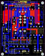
For all ground plane researchers, I present here the best IMO implementation of a PCB for a GC. To me it's still a standard by which all other designs are measured (not to mention that many people prefer my amps though😉)
As you look at this board, you see that ground plane is shared for the caps and for the signal, no other special arrangements were taken. Brian's board design was also influenced by Kusunoki layout, yet some additional measures were taken to separate SG, as the main ground plane was bigger. When I look at Brian's board, I can't hide my admiration for layout choices and overall appearance. This thing is simply cute and could be regarded as the next standard by which other boards are measured.😉
I've also built few amps with that board and didn't notice and problems with noise and performance matches my p2p efforts.
When I make amps in p2p fashion, I also tried running grounds in different ways, and I didn't observe any differences when signal ground was routed separately, or if it's connected directly to common point (on a binding post). So I do it the way that is most convenient. No complains from customers either and amps run extremely quiet.
One thing that I take care of, is connecting both OG with thick wire (in stereo amp), otherwise the amp picks up high frequence garbage.
So I'm not disussing this theoretically, but I'm talking from experience, after building many amps, in many different configurations.
Attachments

Going underground
This "ground plane researcher" will be performing his detailed, meticulous, theoretically complex, not to mention highly misunderstood investigations underground for awhile so as not to bother the peace-loving surface folk
 .
.
BTW I agree that Brian's 3875 layout is very cute (9/10 on the CF scale) and greatly appreciate that project.
Oh, BTW#2, Peter, you're pcb original standard looks to have approximately half the ground noise compared with Brian's, but only 1/10 CF.
-Robert
This "ground plane researcher" will be performing his detailed, meticulous, theoretically complex, not to mention highly misunderstood
investigations underground for awhile so as not to bother the peace-loving surface folk. BTW I agree that Brian's 3875 layout is very cute
(9/10 on the CF scale) and greatly appreciate that project.Oh, BTW#2, Peter, you're pcb original standard looks to have approximately half the ground noise compared with Brian's, but only 1/10 CF.
-Robert
- Status
- Not open for further replies.
- Home
- Amplifiers
- Chip Amps
- LM4780 pcb layout and others