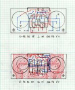
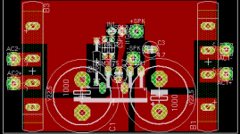
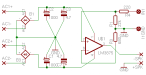
Here's the proposed layout. The board is using minimized circuit (same type as for LM3875). I put together LM4780 amp this way and it works fine. The board's size is only 0.1" bigger than currently available board from Brian (on shorter side). It's parallel version, and I didn't really find a need for stereo amp with this chip.
There is only one jumper used (for input ground). The muting resistors are SMD type. All other resistors are Caddocks and Rikens. I used Mills 0.22, 5W for output. Capacitors are either 1000u BG or 1,500u Panasonic FC. Feedback resistors are mounted on board this time.
I believe Brian might transfer this into proper PCB format😉
Attachments
"I believe Brian might transfer this into proper PCB format"
ahmm... Brian... you listening... 🙂
Well I guess now the big question is how does it sound?
What about compared to the LM3785 GC's?
I was waiting on a paralled or bridged design based off of Brian's GC PCBs for the LM3785 since I have a few. I'm glad you did this in a parallel version. If these sound as good as the GC's maybe I'll do these paralleled & not worry about the others.
I actually built it and compared to LM3875. It's not bad at all.
There may be some differences, but nothing major. I left it for evaluation with a friend of mine, and I will know more later, when it's completely broken in.
There may be some differences, but nothing major. I left it for evaluation with a friend of mine, and I will know more later, when it's completely broken in.
More interest
I'm interested in this project in order to make a 3-way stereo amp for integrating with a pc music system. Hi gets one board. Mid gets another. Lo gets 3rd.
I love the new layout emerging from Peter. Much better minimization of routing.
Please consider something I've been experimenting with (in Eagle only) which is putting the amp on one side of the board and the major components on the other. This allows the big capacitors to sit very close to both the supply pins of the ic as well as the common ground point.
Another preference for me is to compact the layout of the interior of the box by integrating the ps either on the same board as the amp (which I prefer) or to plan on bolting the 2 together closely and running simple short straight bare wiring between directly opposing pads.
When you start thinking like that (or should I say "if") then a much more layout friendly rectifier bridge is the SIP11 package which has 4 inline leads (+ ac ac -). It is extremely easy to layout the supply for the board with 2 of these! I just don't know if the sonics would hate them however .
.
Anyway, I'm in as long as you don't use the National layout and it is not a mandatory bridged setup. Don't care about bridging.
-Robert
I'm interested in this project in order to make a 3-way stereo amp for integrating with a pc music system. Hi gets one board. Mid gets another. Lo gets 3rd.
I love the new layout emerging from Peter. Much better minimization of routing.
Please consider something I've been experimenting with (in Eagle only) which is putting the amp on one side of the board and the major components on the other. This allows the big capacitors to sit very close to both the supply pins of the ic as well as the common ground point.
Another preference for me is to compact the layout of the interior of the box by integrating the ps either on the same board as the amp (which I prefer) or to plan on bolting the 2 together closely and running simple short straight bare wiring between directly opposing pads.
When you start thinking like that (or should I say "if") then a much more layout friendly rectifier bridge is the SIP11 package which has 4 inline leads (+ ac ac -). It is extremely easy to layout the supply for the board with 2 of these! I just don't know if the sonics would hate them however
.Anyway, I'm in as long as you don't use the National layout and it is not a mandatory bridged setup. Don't care about bridging.
-Robert
Peter Daniel said:Here's the proposed layout. The board is using minimized circuit (same type as for LM3875). I put together LM4780 amp this way and it works fine. The board's size is only 0.1" bigger than currently available board from Brian (on shorter side). It's parallel version, and I didn't really find a need for stereo amp with this chip.
There is only one jumper used (for input ground). The muting resistors are SMD type. All other resistors are Caddocks and Rikens. I used Mills 0.22, 5W for output. Capacitors are either 1000u BG or 1,500u Panasonic FC. Feedback resistors are mounted on board this time.
I believe Brian might transfer this into proper PCB format😉
Looks pretty good. I just got home from my traveling a little bit ago. I will look into this soon.
--
Brian
You might be able to use a previous board as template for some parts of this new layout😉
As to putting caps on amps site and other components on the bottom. It is good approach, but in this case, placing caps to close to one another, blocks the access to mounting screws on the chip and it's impossible to mount/remove the chip from heatsink without removing caps first. Also, with that type of power supply connection points, the caps are pretty close enough.
Installing Caddocks on bottom would require more space than usually, as those are specifically shaped resistors (high footprint).
Peter,the layout is very compact.Do you consider use smd resistors? I think the board design is minimized and more perfect performance electricity.
-digi
-digi
Peter Daniel said:You might be able to use a previous board as template for some parts of this new layout😉
As to putting caps on amps site and other components on the bottom. It is good approach, but in this case, placing caps to close to one another, blocks the access to mounting screws on the chip and it's impossible to mount/remove the chip from heatsink without removing caps first. Also, with that type of power supply connection points, the caps are pretty close enough.
Installing Caddocks on bottom would require more space than usually, as those are specifically shaped resistors (high footprint).
I can use the same libraries from the last project. I also already have the 0.22ohm mills resistor footprint created from the LM3886 layout I am working on.
It shouldn't take too long, but I need to reformat my computer first tommorrow, as my hard drive is dying, developing bad sectors. I have the new one, so it shouldn't take too long (covered under my laptop warranty). After this, I will reinstall the pcb software, and work on the layout.
--
Brian
digi01 said:Peter,the layout is very compact.Do you consider use smd resistors? I think the board design is minimized and more perfect performance electricity.
-digi
Only two SMD resistors (10K) are used, for mute function. It's almost an obsession with me to make a circuit smaller😉
peter,
this my SMD boards,stereo versions.I have used 1/4W film smd resistors for Rin,mute,and gain setting pair.the layout still needs optimizing, I think that will also be more mini.
btw,I have separated the output 0.1ohm/3W resistors from boards.
cheers~!
this my SMD boards,stereo versions.I have used 1/4W film smd resistors for Rin,mute,and gain setting pair.the layout still needs optimizing, I think that will also be more mini.
btw,I have separated the output 0.1ohm/3W resistors from boards.
cheers~!
Attachments
Layout style
I could tell that it wasn't clear what I was talking about earlier so I'm posting how I've been fooling with an alternate layout (but still on LM3875 but the style is relevant).
1. Moved chip inboard to give room for power supply routing in back.
It is easy to apply a heatsink to this, but no need to explain atm.
2. Caps are mounted below the board, everything else above.
3. Unused pins of 3875 were chopped off and pads omitted.
Note feedback resistor can easily come in from behind now (ptp).
4. In-line SIP11 bridges are onboard.
Layout was put together in 30 minutes. NOT OPTIMIZED YET!!! Size is 2.8 x 1.6".
Just showing potential of this style.
-Robert
Attachments
"I just got home from my traveling a little bit ago."
Ok Brian I see how it is now.... You go to FL & now that you're "married" you can't come hang out with your single buddy.... 😀
Ok Brian I see how it is now.... You go to FL & now that you're "married" you can't come hang out with your single buddy.... 😀
RF, check the R3, should go in an isolated trace directly to speaker ground. Feedback, is this resistor soldered directly into LM3875?
Re: Layout style
It is a nice layout and very compact, but good only for a certain, specific application, and not very universal.
Although it may seem more compact than the board that Brian is offering presently, it is also very limited in functionality. You cannot use it everywhere and the size and the way a chip is mounted cause too many restrictions. With Brian's board, I already made 6 different amps and I had no problem implementing it. That's the beauty of this design: functionality.
It is tempting to use SMD parts: resistors and bridges, but I don't know what can I expect from those parts soundwise. The parts that are currently being used, are guaranteed to sound well and they were being optimised and selected over the period of a year.
The chip should be possible to mount directly to the heatsink, without additional brackets. Also, what is the influence of rectifiers in such close proximity to the chip?
RFScheer said:I could tell that it wasn't clear what I was talking about earlier so I'm posting how I've been fooling with an alternate layout (but still on LM3875 but the style is relevant).
1. Moved chip inboard to give room for power supply routing in back.
It is easy to apply a heatsink to this, but no need to explain atm.
2. Caps are mounted below the board, everything else above.
3. Unused pins of 3875 were chopped off and pads omitted.
Note feedback resistor can easily come in from behind now (ptp).
4. In-line SIP11 bridges are onboard.
Layout was put together in 30 minutes. NOT OPTIMIZED YET!!! Size is 2.8 x 1.6".
Just showing potential of this style.
-Robert
It is a nice layout and very compact, but good only for a certain, specific application, and not very universal.
Although it may seem more compact than the board that Brian is offering presently, it is also very limited in functionality. You cannot use it everywhere and the size and the way a chip is mounted cause too many restrictions. With Brian's board, I already made 6 different amps and I had no problem implementing it. That's the beauty of this design: functionality.
It is tempting to use SMD parts: resistors and bridges, but I don't know what can I expect from those parts soundwise. The parts that are currently being used, are guaranteed to sound well and they were being optimised and selected over the period of a year.
The chip should be possible to mount directly to the heatsink, without additional brackets. Also, what is the influence of rectifiers in such close proximity to the chip?
Agreed
Peter you are probably mostly at least partly right in your assessment (well...ok).
One point that I DO think makes sense is to clip N/C leads and omit their pads to gain routing freedom and especially wider tracks.
Regarding AC so close, I doubt it would help sound much but is just more compact. If there's any emi from ~30VAC, I would just erect a nice looking grounded copper fence to make good neighbors.
Regarding in-line bridges, you're right that it's a risk not worth taking unless it's been tested. I'm rather newbyish and so haven't seen the history of testing power supply components. Can't quite understand why those MUR860's would sound better. They're really nothing special. If it's less ringing of the transformer or something like that, it's really easy to verify with a scope. My problem with that though is that it won't be consistent with different transformers, ac routing wire lengths and capacitor selections. Would anyone benefit if I set up an experiment to test different bridges?
Anyway, was just putting the layout ideas out there in case one thing led to another. Thanks for the crit. That's my 3rd pcb layout and doing these is a reasonably fast way to play with variations and get to know the circuit better.
Peranders, in my layout ground is ground is ground. No stars or separation of signal and power. Goal is minimum track length resistance and inductance to ground for all components. If ground still has too much resistance, I would solder a bussbar to the plane, but I think it would work well without.
The feedback resistor is added much as we do now point to point but would lie underneath the raised ic and leads would come in with less interference from the back.
On with the 4780!
-Robert
Re: Agreed
I real life currents creates voltage drops, groundplanes not excluded! If you have ampere currents just beside sensitive (yes!) feedback paths you will get degraded performance.RFScheer said:Peranders, in my layout ground is ground is ground. No stars or separation of signal and power. Goal is minimum track length resistance and inductance to ground for all components. If ground still has too much resistance, I would solder a bussbar to the plane, but I think it would work well without.
Groundwork...
Some advice for you guys - shorten the electrical path between the PSU reservoir caps 0V point.
Some of the boards above have them at extreme ends of the PCB, with a ground plane connection running across the board. You then have sensitive low-level signals referenced to a point with high current flows and finite impedance.
There will be significant current flows across the ground plane as a result of this, and depending upon how the rest of the connections go to ground this will likely introduce audible, and measurable, effects.
Ground rarely is ground, in reality. All traces and planes have finite impedance, it's worth considering this more closely.
Andy.
Re: Groundwork...
Is this in relation to star grounding? are you saying the star point should be as close to the cap as possible?
ALW said:Some advice for you guys - shorten the electrical path between the PSU reservoir caps 0V point.
Some of the boards above have them at extreme ends of the PCB, with a ground plane connection running across the board. You then have sensitive low-level signals referenced to a point with high current flows and finite impedance.
There will be significant current flows across the ground plane as a result of this, and depending upon how the rest of the connections go to ground this will likely introduce audible, and measurable, effects.
Ground rarely is ground, in reality. All traces and planes have finite impedance, it's worth considering this more closely.
Andy.
Is this in relation to star grounding? are you saying the star point should be as close to the cap as possible?
- Status
- Not open for further replies.
- Home
- Amplifiers
- Chip Amps
- LM4780 pcb layout and others