Hi everyone,
I was wondering if I could get some help with an issue I'm having with a chipamp build.
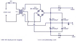
I built it using the TDA2050 snubberized power supply: View attachment 952344
It hums, a lot. It has a very loud 100hz hum (I'm in the UK).
I have played around with a cheap digital scope I have, and it seems like the issue is with the +ve supply, which has 1.5v of a sawtooth 100hz signal in it. It's also slightly lower in voltage output (~20v compared to -25v -ve, which is what I expected).
View attachment 952347
This signal is exactly mirrored on the output too.
On the -ve, there is the same signal, but only around 25-30mv:
View attachment 952346
Interestingly (maybe), the mirrored signal on the output disappears if I touch the audio input. If I touch the audio in on the right channel, the right sawtooth output signal disappears at the right speaker terminal, but it remains on the left. If I touch the left in, it disappears on the left out but not the right.
I've tried moving the wires around, changing ground positions, moving the transformer, no change. The rectifier tests OK.
The only thing I haven't done is change the 10,000uf cap on the +ve rail, which I'm going to do today. It was a brand new Nichicon cap, does it seem possible that this is the problem and it's just not getting smoothed?
It seems like something else might be going on.
View attachment 952345
You have done the primary homework yourself. Few inputs though:
using a dual bridge rectifier has its advantages but without a PCB I don't recommend it at all.
If I were in your position I would disconnect the PSU from the power amp, remove one leg of the bleeder resistor, use only one bridge.
First check the output voltage at each rail with a 18+18 volt trafo it should be [(18*1.414)-1.4) ballpark 24 volts might have messed up the formula a bit but voltage should be around 24 on each rail, I would add an error margin of 10% on each rail so it should be between 21.6 to 24 volts on each rail.
Second check the ripple on each rail if the capacitors are not out of order and one of the rectifiers in the bridge is not shorted and ground is properly connected the ripple should be minimal.
Oscillation at 100Hz means lack of ground. You need to check that.
With a good psu power amp do not oscillate except they are connected to a poor Pre, turntable without ground.
Hum or oscillation at 100 hz is most of the time due to psu, and the mostly likely responsible candidate is Ground connection or capacitors. In your case I'll put my money on "improper ground"
Last edited:
OK, I will move the tail end of the resistors.
Right now, there is the same level of hum with either of the left or right inputs inserted separately or with both inserted. The only difference is the hum only comes out of one speaker with only one input inserted.
The only time it's silent is when nothing is connected at the input.
rehanabid, the oscillation has now stopped. There is a little bit of a ripple left in each side of the supply, but less than 50mv. I checked the diodes on the respective pins of the bridge rectifiers and they were fine. Do you have a schematic for the power set up you're talking about? If it would be better I can look at changing to that further down the line.
Thanks everyone for your help so far.
Look at the diagrams in post #116, 122, 125, 131 and 133. You have to follow the same methods.
Complete novice alert! *don't read if easily annoyed by stupid questions*
Complete novice alert! *don't read if easily annoyed by stupid questions*
savt22, take care if you change riders now. Has your new jockey jumped on the whip before reading the form so far? You might be on a winner, but keep your eye on the track.
you can use single bridge rectifier as mentioned in this schematic. Remove the bleeder resistor for now. 1R/1watt.
First use a single bridge, if the hum persists (which I doubt) try and change the source audio signal and cable. e.g if you are using a tape/reel to reel/phono(pre out) as the source change it to may be PC audio out.
try and change the cable from which you are giving the audio input (RCA cables or 3.5 mm cables)
Attachments
Thanks again everyone.
I realised that the schematic I uploaded was missing a couple of 100nf capacitors that, Mooly, you'd recommended on the Complete novice alert! thread. The schematic that came with the paperwork for the PCB didn't include them, so I missed them off when I was quickly adding the values and the inductor to the schematic from the documentation.
I have ordered the parts for the Zobel, however, and some additional 10R resistors.
In the meantime, I moved the input RCA grounds from the PCB to the capacitors' ground, and that has eliminated all but a tiny hum. There's now a very faint 'on' sound now, that registers as around 50mv of general 'noise' at the speaker terminals on the scope. It'd still be nice to get rid of that, though, but I can listen to music without issue and it sounds excellent.

:'(
I'm not sure what happened. Like I said, it was working fine. Small hum but nothing terrible. Hooked it up to the pre-amp, everything was still fine.
Turned it on and off a bunch of times while I was trying to decide whether I preferred it with or without the pre-amp. No issues.
Then, turned it on, heard a pop/crackle immediately, saw smoke, turned it off. Chip's burned. It looks like it was between pins 3, 4, and 5. I wonder if there was a short or something, or if it was connected to turning my pre-amp on at the same time.
I have some more chips coming in the post along with the parts for the zobel and the 10R resistors... and a much bigger heatsink, just incase that was a contributing factor.
I'll have a break from it until the new parts come. I'm gutted!
...and a much bigger heatsink, just incase that was a contributing factor.
I guess you haven't read the LM4766 datasheet which is the first thing to do when dealing with IC...if you did you would certainly have some questions regarding the equations on page 15 "DETERMINING THE CORRECT HEAT SINK".
It's truly amazing how much LM4766 has ever withstand so much overheating with such a tiny heatsink...and rest assured it has done absolutely everything to protect itself from abuse, but the poor thing couldn't take it anymore.
One more thing...the metal tab on the LM4766 is at Vee potential, so -25VDC is also there on the heatsink in your case, because you are not using an insulator between the LM4766 and the heatsink. Therefore, if the contact between the heatsink and the housing accidentally occurs, you have a short circuit.
Edit... one more note, never connect/disconnect interconnects while the amplifier is on, even though the LM4766 has some protection for that as well.
Last edited:
The circuit you posted (post #7) was always a very simplistic implementation pretty much lifted from the data sheet.
Apart from the error of the missing resistor at the input, the input should really be AC coupled and also include an RF filter. An output inductor should be included to aid stability into slightly capacitive loads and of course the Zobel network.
Apart from the error of the missing resistor at the input, the input should really be AC coupled and also include an RF filter. An output inductor should be included to aid stability into slightly capacitive loads and of course the Zobel network.
Thank you. As aparatusonitus pointed out, I think my mistake was connecting the interconnects while it was on. I didn’t realise that was something to avoid. That was when it started smoking. I was connecting it while switching it on.
Well, I’m certainly learning a lot!
I’m a bit disappointed with the board I bought to be honest, I did think that it should just be a case of populating the board and it working, and anything ‘extra’ I’d seen was more optional. Obviously that was not the case, but I feel like that should have been made clearer.
I had already added in the inductor on the output, and will add the zobel too.
For an rf filter, would that just be a small capacitor (120pf-ish?) across the input resistor to ground?
For the ac coupled input, would a 4.7uf capacitor in series with the source signal be sufficient?
Finally, I have been reading more about grounding. I am going to run all the grounds off board to the star ground rather than connecting to the pcb’s ground plane.
Can I just check where I need to put the 10R resistors? I saw an implementation which focused on using the 10R resistors between the signal ground and the power ground.
My thinking was therefore lifting the legs of the two 22uf dc shunt caps that connect to ground in the feedback loop, and inserting two 10R resistors between these and ground. Then, connect the signal ground from the RCA inputs to immediately before each of that channel’s respective 10R resistor too, so between the shunt cap and the ground lift resistor. From reading my reading, that sounds like it will fix any lingering hum issues. Does that sound right?
There were a few LM3886/LM1875 schematics with something similar, which I have screenshotted here.
Last edited:
When you add the Zobel network remember that it goes before the inductor, not after.
A 120pF (or 220pF) across the input resistor (the one from the chip to ground) should be OK but you then should add a series resistor in front of it all, say 2k2 or 4k7.
A 4.7uF coupling cap is OK. Fit the polarity to suit the small voltage present at the input pin which could be a few tens of millivolts negative.
Grounding is a massive topic and something that has to be considered from the outset. You can certainly try what you propose, many designs use that technique.
There’s already a 1k resistor in series with the input, would that be ok? Or did you mean in series with the rf cap to ground?
Ok. I will buy these additional parts and report back when I’ve installed everything.
Ok. I will buy these additional parts and report back when I’ve installed everything.
For an rf filter, would that just be a small capacitor (120pf-ish?) across the input resistor to ground?
It will be ok, but the ground reference resistor in parallel with the rf filter capacitor must be on the right side of the input 1k resistor towards the input pin (8/13) to be effective.
For the ac coupled input, would a 4.7uf capacitor in series with the source signal be sufficient?
Yes, but put a film type capacitor, not an electrolyte of any kind.
Finally, I have been reading more about grounding. I am going to run all the grounds off board to the star ground rather than connecting to the pcb’s ground plane.
Don't do it...we don't know how well or badly grounding has been done, stick to what you have for now.
Can I just check where I need to put the 10R resistors? I saw an implementation which focused on using the 10R resistors between the signal ground and the power ground.
My thinking was therefore lifting the legs of the two 22uf dc shunt caps that connect to ground in the feedback loop, and inserting two 10R resistors between these and ground. Then, connect the signal ground from the RCA inputs to immediately before each of that channel’s respective 10R resistor too, so between the shunt cap and the ground lift resistor. From reading my reading, that sounds like it will fix any lingering hum issues. Does that sound right?
Sounds like a good plan...that's where I intended to put them when I first mentioned them.
Great! Ok, there’s a plan. I will order the coupling and rf caps, add those and the zobel network, replace the chip, and use the 10r resistors to lift the signal ground but leave the rest.
Thanks again for your help, I’ll update in a few days.
Thanks again for your help, I’ll update in a few days.
I did all of the above, and it is now completely working! Thanks again for all your help.
There's now no general noise whatsoever, at least as far as I can hear. I also re-did a lot of the wiring (including twisting the -/+ve wires running to the board) as I'd burnt a couple of them from soldering/re-soldering. It's a lot neater now.
It's picking up a tiny bit of noise from my computer mouse when I move it, but I've still got the lid off and it's extremely minimal (sounds like a very faint rustling) and I can't hear it when music is playing. It's hooked up to my computer too, so that could be a factor.
It's a little hard to say, and obviously I haven't A/B'd it, but I definitely think it sounds just a touch less 'airy' than before. That's being very picky though.
Interestingly, it is A LOT louder now for some reason - before it would distort quite quickly, about 1/3 of the way up. It could be loud enough for just listening while working, but it wasn't 'loud' by any means. I'd just assumed that was a loud as it got, but this thing now gets unreasonably loud, so...
The old chip and new chips also look a bit different, the old one had 'U1' stamped on sideways and off-centre, while the new ones have 'T1' stamped vertically and centred. The fonts are also different.
Last edited:
There's now no general noise whatsoever, at least as far as I can hear. I also re-did a lot of the wiring (including twisting the -/+ve wires running to the board) as I'd burnt a couple of them from soldering/re-soldering. It's a lot neater now.
Ok, show us what your wiring looks like now...also, if by any chance you have a blank pcb, show us the top and bottom side.
It's picking up a tiny bit of noise from my computer mouse when I move it, but I've still got the lid off and it's extremely minimal (sounds like a very faint rustling) and I can't hear it when music is playing. It's hooked up to my computer too, so that could be a factor.
Regardless of the amplifier lid, you will have a problem as long as the signal source is PC...if the signal coming out of it is not galvanically isolated (which is not n your case, so PC SMPS interference through grounding reaches the amplifier and is superimposed on the output signal).
It's a little hard to say, and obviously I haven't A/B'd it, but I definitely think it sounds just a touch less 'airy' than before. That's being very picky though.
Interestingly, it is A LOT louder now for some reason - before it would distort quite quickly, about 1/3 of the way up. It could be loud enough for just listening while working, but it wasn't 'loud' by any means. I'd just assumed that was a loud as it got, but this thing now gets unreasonably loud, so...
Don't go into sound quality (yet)...there will be time for that.
The old chip and new chips also look a bit different, the old one had 'U1' stamped on sideways and off-centre, while the new ones have 'T1' stamped vertically and centred. The fonts are also different.
If you bought them from legitimate sources like Mouser, Farnell, etc., there is no reason to worry.
One more thing...the 10uf electrolytic capacitors left and right of the LM4766 need to be replaced with quality ones of at least 470-1000uF/35VDC.😉
I did all of the above, and it is now completely working! Thanks again for all your help.
Well that's great

The 'loudness' thing is difficult to comment on without actual tests. You would need to look with a scope at the output and see what and where it clips at and whether the output looks clean.
If all you did was replace the chip then perhaps there was some issue with the first one.
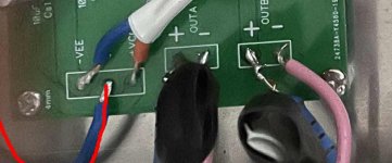
I just stumbled across and saw something which really should be fixed.

These wires got way too much insulation removed and can short out easily, the soldering does not that great either. They don't even need a broken solder point for that. In terms of safety and reliability this definitely needs to be adressed.
These wires got way too much insulation removed and can short out easily, the soldering does not that great either. They don't even need a broken solder point for that. In terms of safety and reliability this definitely needs to be adressed.
Attachments
- Home
- Amplifiers
- Chip Amps
- LM4766 Hum Issue (first chipamp build)