Heat problems
This version also may suffer similar heat problems as the commercial one because the power transistors for both the channels are close on the heat sink. What is the power output these boards are targetted for?
Routhun.
This version also may suffer similar heat problems as the commercial one because the power transistors for both the channels are close on the heat sink. What is the power output these boards are targetted for?
Routhun.
Re: Heat problems
Mine can deliver about 2 x 100W (THD - 0.001%). I will use two of this boards to make symmetrical amplifier (+ OPA1632). Spaces between transistors are big enough and LM4702 won't be mounted on the same heat sink.
routhun said:This version also may suffer similar heat problems as the commercial one because the power transistors for both the channels are close on the heat sink. What is the power output these boards are targetted for?
Routhun.
Mine can deliver about 2 x 100W (THD - 0.001%). I will use two of this boards to make symmetrical amplifier (+ OPA1632). Spaces between transistors are big enough and LM4702 won't be mounted on the same heat sink.
Re: Re: Heat problems
I have been running a similar amp for months now, but my power modules are separate from the driver, and can be just about anything. My prototype uses SAP16s. I actually have a whole thread about it.
http://www.diyaudio.com/forums/showthread.php?postid=949032#post949032
It is working quite well, but I think I am onto something I like even better. 🙂
I have not posted to the thread in a while, a lot of the PCBs/schematics have actually changed, but the concept is the same, and works quite well.
I have also designed (but not implemented yet) over current protection and a soft start thanks in no small part to my friend Mauro Penasa.
Cheers!
Russ
veteran said:
Mine can deliver about 2 x 100W (THD - 0.001%). I will use two of this boards to make symmetrical amplifier (+ OPA1632). Spaces between transistors are big enough and LM4702 won't be mounted on the same heat sink.
I have been running a similar amp for months now, but my power modules are separate from the driver, and can be just about anything. My prototype uses SAP16s. I actually have a whole thread about it.
http://www.diyaudio.com/forums/showthread.php?postid=949032#post949032
It is working quite well, but I think I am onto something I like even better. 🙂
I have not posted to the thread in a while, a lot of the PCBs/schematics have actually changed, but the concept is the same, and works quite well.
I have also designed (but not implemented yet) over current protection and a soft start thanks in no small part to my friend Mauro Penasa.
Cheers!
Russ
I have also designed (but not implemented yet) over current protection and a soft start thanks in no small part to my friend Mauro Penasa.
Can this be used for other amp designs to?
Regards
Re: Heat problems
You make a correction for the length of the heatsink. The correction factors are on Aavid Thermalloy's website.
routhun said:This version also may suffer similar heat problems as the commercial one because the power transistors for both the channels are close on the heat sink. What is the power output these boards are targetted for?
Routhun.
You make a correction for the length of the heatsink. The correction factors are on Aavid Thermalloy's website.
GeWa said:
Can this be used for other amp designs to?
Regards
Well the only part I have finished is the soft start (it works great) and it is good for 10amps or so. So any amp that draws less then that from the mains should be fine. It is its own PCB. It also works for either 110 or 220 volt mains just by changing a couple values.
I will keep you posted on the over-current protection. That one is a lot more tricky to get right and needs to be tweaked for each particular circuit.
Cheers!
Russ
You can use the mute function on the 4702 for over-current protection -- although you can't smoothly cut off the drive -- use a comparator and a flip-flop so that the offending condition can be rectified (are male teenage son's offending conditions?)
jackinnj said:You can use the mute function on the 4702 for over-current protection -- although you can't smoothly cut off the drive -- use a comparator and a flip-flop so that the offending condition can be rectified (are male teenage son's offending conditions?)
A very good point/suggestion, and worth trying. I may see if I can work this out. I may post something for you guys to look at. Protection circuits are still new to me.
To add to the mute pin usefulness, I think Pinkmouse suggested a while back using the mute pin coupled via capacitors to make a soft start. I'll have to look back for the exact circuit, but the gist was the charging of the caps brought the mute pin up and turned the output on. I believe that was from a National data sheet originally. . . .
Oh well, I can't remember specifics, but it seemed a great idea at the time and was quite straight forward if memory serves.
David
Duh! I just found the thread here
Oh well, I can't remember specifics, but it seemed a great idea at the time and was quite straight forward if memory serves.
David
Duh! I just found the thread here
Looking for input
I am building a speaker protection circuit for use with my 4702 amp as well as others.
I have posted about it here:
http://www.diyaudio.com/forums/showthread.php?s=&threadid=91146
Some of you may have interest and input. Your ideas would be welcome.
Cheers!
Russ
I am building a speaker protection circuit for use with my 4702 amp as well as others.
I have posted about it here:
http://www.diyaudio.com/forums/showthread.php?s=&threadid=91146
Some of you may have interest and input. Your ideas would be welcome.
Cheers!
Russ
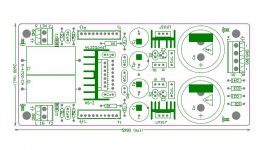
Finally weekend and some free time 😉. My new LM4702 amplifier:
schematic
PCB
Protection circuits... few photocouplers + atmega + thermal sensor + relays 😉 It's easy.
An externally hosted image should be here but it was not working when we last tested it.
schematic
PCB
Protection circuits... few photocouplers + atmega + thermal sensor + relays 😉 It's easy.
Has anyone experimented with the capacitor between source & sink (LM4702) NS have Cb3/5 as 0.015/1250v polyprop (I used a 0.015/300v Mica) Have tried other value caps but the 0.015 sounded best?

I don't know that you want the output connections so closely associated with the input connections.
VLSI said:Has anyone experimented with the capacitor between source & sink (LM4702) NS have Cb3/5 as 0.015/1250v polyprop (I used a 0.015/300v Mica) Have tried other value caps but the 0.015 sounded best?
I haven't done any sound comparisons, but I've seen a huge range of values of the capacitor in this position (across the Vbe multiplier). 0.015uF is on the low side, 47uF electrolytic is the highest I've seen, in Randy Sloan's book. Without it I think there is high frequency distortion at high output levels. 0.1uF seems to be a very common compromise. Because the cap is in a NFB loop its sonic signature would be miniscule.
Re: New design for LM4702CTA
Lovely, now you can use few different output stages with one, LM4702-base board 😉
monkey29 said:LM4702C-V.2
Lovely, now you can use few different output stages with one, LM4702-base board 😉
Re: Re: New design for LM4702CTA
David
You and I have both done the math for that one! My bet is that the power from the LM4702 wouldn't be up to scratch for driving more than one board. I think you would have to put an intermediate current gain stage before the output boards to drive more than one. Of course I don't have the numbers for that particular system, but my back-of-the-envelope math says "not quite."veteran said:Lovely, now you can use few different output stages with one, LM4702-base board 😉
David
Hi David,
I think he meant that one could experiment or support multiple output configurations, but only one at a time...
I am enjoying my mine... Very transparent sound.
Dale
I think he meant that one could experiment or support multiple output configurations, but only one at a time...
I am enjoying my mine... Very transparent sound.
Dale
- Status
- Not open for further replies.
- Home
- Amplifiers
- Chip Amps
- Lm4702