Let's see if they work first -- when I first did the layout I had the P and N devices reversed. Talk about maddening !!!
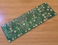
the darlingtons go on the bottom, so the PCB will mount on the heat sink.
the darlingtons go on the bottom, so the PCB will mount on the heat sink.
Hi,
If DIYAUDIO is "by the fanatics and for the fanatics" were are the 100-200 watt and 200-300 watt theory models from the LM4702 driver?
Just an odd idea over 100 watts.
Peace,
Mark
If DIYAUDIO is "by the fanatics and for the fanatics" were are the 100-200 watt and 200-300 watt theory models from the LM4702 driver?
Just an odd idea over 100 watts.
Peace,
Mark
Hey Mark,
If you want to try some things out, I am sure the rest of us would be interested in seeing what you came up with. As a starting point, I would try a simple voltage follower and add in a couple more ouput pairs. Let us know the configuration when you get it working.
David
If you want to try some things out, I am sure the rest of us would be interested in seeing what you came up with. As a starting point, I would try a simple voltage follower and add in a couple more ouput pairs. Let us know the configuration when you get it working.
David
Boards
David I sent you an email regarding boards, I hope you get it.
How easy will this be for a pleb such as myself to get this running?
Brett.😉
David I sent you an email regarding boards, I hope you get it.
How easy will this be for a pleb such as myself to get this running?
Brett.😉
Brett,
Short answer, pretty easy, but one step over a chipamp. Still, well within reason. I'll post specifics as to what I am doing with the boards I made over in the groupbuy thread.
David
Short answer, pretty easy, but one step over a chipamp. Still, well within reason. I'll post specifics as to what I am doing with the boards I made over in the groupbuy thread.
David
It will be quite easy to build something more powerful than GC keeping this as simple as it can be. I'm planing to integrate some protection circuits on the board - this should be useful especially for novice 😉
Dfdye is making excellent job here testing various output stages. I will place some more info about how it plays with MOSFETs.
Dfdye is making excellent job here testing various output stages. I will place some more info about how it plays with MOSFETs.
An externally hosted image should be here but it was not working when we last tested it.
if you are going to use the Sanken devices (SAP16N & P) which are 5 pin TO-247 devices, note that pins are a bit spade-like (i.e. flattened from round) thus the tip is actually 31.5 mils (0.8mm) and the leg is 25.5 mils (0.65mm). You probably have to create your own device in your CAD system.
I am drilling them out to 35 mills.
I am drilling them out to 35 mills.
Yes, I know that 😉. I'm planing to implement them in a future (SAP15/16) - this boards is for standard, TO3P darlington or MOSFET transistors.
There is no need to make wholes bigger than 0.8mm - after drilling and cladding they will have about 0.85mm on final board.
What CAD program do You use?
There is no need to make wholes bigger than 0.8mm - after drilling and cladding they will have about 0.85mm on final board.
What CAD program do You use?
Attachments
Which parts actually come with the kits? Can someone give me an idea of which modules to order?
The commercial part of this thread has been split off.
Eventually, it might reappear in the Vendors bazaar.
/Hugo
Eventually, it might reappear in the Vendors bazaar.
/Hugo
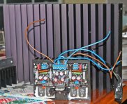
Work in progress -- these massive heatsinks were so cheap i bought 20 of them, but they are the most ungainly critters to work with -- i had to mill a little bit of clearance for the output devices -- there will be a small RS fan on each heatsink to move a bit of air through them. they measured out at 0.7 C/W when used chimney style. the cap shown in the picture is 10mF, but I have some 39mF's in my Hafler 220 which will be pressed into service here:
An externally hosted image should be here but it was not working when we last tested it.
just a Vbe multiplier, potentiometer and resistors -- standard stuff.
the heat sinks are mounted on 5/8" hexagonal 4-40 spacers which I also purchased surplus.
the heat sinks are mounted on 5/8" hexagonal 4-40 spacers which I also purchased surplus.
sound impressions of 4702 kit
My lm4702 kit arrived yesterday, it used SAP15s in the output stage. I've wasted no time in connecting it. Used a dual +42.5v - 0 -42.5v power supplies from a old vector research amplifier to power this module. Pre-out of denon pra-1000 preamplifier is used as the input to this module. This preamp is modded by replacing the linestage opAmp with lm4562.
Sound is neutral but powerful, detailed but not harsh, precise and musical with very good soundstage. Sometimes I wonder how can this module powered from just 42v supplies can deliver such an awesome power? It just controls the speaker effortlessly. Build one for yourself, you'll never be disappointed.
-Routhun
I got one too. Very professional. What is your DC offset voltage. On one channel I get about 6-9mV. I had trouble setting the proper bias until I replaced the 75Ohm base resistor with a jumper.
How hot does your heat sink get. Mine gets pretty warm if I push it hard. Very clear. Should work great for my active speaker system.
Dale
How hot does your heat sink get. Mine gets pretty warm if I push it hard. Very clear. Should work great for my active speaker system.
Dale
Hi Dale,
On my kit 75ohms resistors were not present instead they were replaced by a short. I didn't change bias settings, bias currents start at 10mA idle and went upto ~50mA by that time heat sink got pretty hot. I guess we need larger heat sinks if we want to push hard. How do you like the sound? Did you compare with any other amps?
Routhun
harvardian said:
How hot does your heat sink get. Mine gets pretty warm if I push it hard. Very clear. Should work great for my active speaker system. Dale
It should get hot -- if you are using the heatsink shown before the commercial part of this thread was deleted you'd see why.
Further -- the output devices function as point sources when they are mounted in such close proximity so the heat has to travel laterally across the sink to be dissipated.
Hi Routhun,
I haven't had time to do extensive testing. Just long enough to make sure it worked and to see how hot the sinks would get. I didn't notice any coloration. The amp seemed quite dynamic. My test speakers are small bookshelfs, so it was hard to determine bass control. I have the regulated front end boards, but don't have an appropriate transformer yet. I used a 36VAC (1KVA). Get about +/-43VDC. No turn on thump...
Guess that it might be time to get out the drill/tap set and use some bigger sinks that I have laying around... The good news is that I can use the old ones as a template.
Of course, it would be difficuult to separate the SAP16's unless they are mounted off board.
Would it be OK to do some flying wires to the devices if I remote mount them?
My LM4702 is NOT mounted on the heat sink. I have some nice fins for it. It didn't even get warm.
Dale
- Status
- Not open for further replies.
- Home
- Amplifiers
- Chip Amps
- Lm4702