It seems a fair number LM3886 of circuits lately have been run at ostensible phase margins that have them oscillating.
What's oscillating in the LM3886 (that quasi-oscillation mentioned in the data sheet) is not the global loop. It's some inner loop somewhere. My money is on a SAT clamp that gets cranky. The loop within the SAT clamp is unstable. In simulation, you will sometimes get convergence issues when this quasi-oscillation occurs. In the lab, this is easily spotted as a buzz on the output waveform as the waveform nears the supply rails. It looks kinda like an AM envelope.
The fix is easy. Use the recommended values for Ri, Rf1, Rf2, Cf, and Cc. Use a Zobel and a Thiele network.
~Tom
Last edited:
Tom, I was more referring to several people's posts (within the chip amp forum) which have had sub-minimum gains and other circuit-based non-idealities.
We're in agreement. 🙂
We're in agreement. 🙂
Many don't read page 1 of the datasheet.
They don't even think about downloading any datasheets.
They want and expect to be spoon fed !
They don't even think about downloading any datasheets.
They want and expect to be spoon fed !
Strip off all the "optional stability components" (Rf2, Cf, Cc). Load the amp with an 8 ohm power resistor. Now run a sine wave into the amp. Crank up the amplitude until the amp starts to clip. You will notice a spurious oscillation near the peaks of the sine wave. I'm guessing it's a saturation clamp inside the LM3886 that oscillates. That's mentioned in the data sheet. National used the term "quasi-oscillation".
I would think, that it does not oscillate but only resonate. Cc reduces gain that much, that there is not much input at resonance frequency. Elsewhere you gave the impression, that, without Cc installed, clipping behaviour was that bad, that the amplifier could possibly not recover. How that? I figure, one should simply not feed the chip slew rates in xcess of 356KV/s (1.4V*2*Pi*40KHz). To that goal, equip input with 2KR2 series, two red LEDs anti-parallel and 1nF8 parallel. I mean, an amplifier is not a wire hence must not be treated as such. It needs bandwidth limiting at its input. People who want to listen to ultrasonics will surely have more sophisticated tools than LM3886s.
I used to design stuff for musicians (me) and sound engineers (me) and considered graceful clipping and reliability very important. To that goal, it was usually necessary to limit amplitude and frequency of input.
One trick for reliability was to have diodes anti-parallel to plus and minus input. On a single-transistor input stage one 1N4148 would do, on an opamp two. But this could cause clipping to become less graceful and ring.
The best design is to limit both inputs, using series resistors and four diodes to ground. I have 42Vcc and 19Vbias, and if gain is 20, then inputs should be limited to +-0.95Vp. I would use an anti-parallel pair of each two 1N4148 in series for negative input, while positive input could be further tweaked for optimum clipping, using Schottky diodes?
Now one could argue, how it should clip, soft or hard. Hard is like "Overdone!", soft is like "Given in!". Passive limiting works the latter way, so i be content with that.
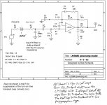
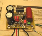
In my 3886 amp project I did a bunch of research, looking at how others did the compensation, looking at the data sheet from TI, modeled what I thought would be best in SPICE, laid out PCBs such that lead lengths and part proximities would be theoretically optimal, built it, and tested it.
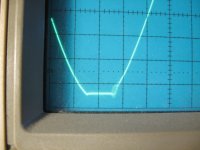
What worked in theory, as usual, didn't quite measure up in practice. There was oscillation at the negative rail with a sine wave, when driven just slightly into clipping. I played around with several part variations until I got the oscillation pretty much gone. Much to my surprise putting a 220p cap across the inputs of the chip actually helped. I'd never done that before, and hadn't intended to use that cap.
My point here is that the parts layout, lead lengths, PCB traces and grounding issues all seem to affect the phase margin substantially, and any high feedback amp should be looked at very closely on the bench to see what actually works best. Theory gives you maybe a good default starting point, but then you want to mess with it until it actually works really well.
The attached circuit might be what I ended up with. I'm not absolutely sure I updated the schematic after the final tweaks, but I think this is close. The best comp part values may well be different for a different PCB layout, or other variables. Simply copying what someone else did may not be optimal. The picture showing the negative rail oscillation is before the final tweaks.
Attachments
Last edited:
I suggest using the values recommended in the LM3886 data sheet for the output Zobel/snubber.
I see no quasi oscillation or buzz in my LM3886 Done Right amp.
Tom
I see no quasi oscillation or buzz in my LM3886 Done Right amp.
Tom
It is quite common BJT amps oscillate a little bit on the edge of clipping. At that point Ft of the output BJT's droops heavily, changing phase margin a lot. Also parts of the amp go into saturation etc. and there is no defined loop behaviour any more. The LM3886 is no exception.
Yep. Devices enter saturation and the loop gain drops like a rock. This causes instability until the devices are brought out of saturation.
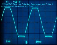
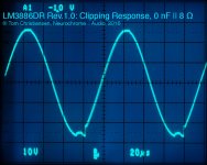
That said, the LM3886 doesn't have to do that. It can be made to not have that little buzz as it recovers from clipping if you follow the directions regarding the Zobel/snubber, Thiele, and decoupling networks given in the application section of the data sheet.
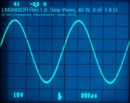
Attached images are from my LM3886DR. You still see the rail-sticking caused by saturation. The devices recover cleanly from saturation.
Tom
That said, the LM3886 doesn't have to do that. It can be made to not have that little buzz as it recovers from clipping if you follow the directions regarding the Zobel/snubber, Thiele, and decoupling networks given in the application section of the data sheet.
Attached images are from my LM3886DR. You still see the rail-sticking caused by saturation. The devices recover cleanly from saturation.
Tom
Attachments
Gents, this is all very fine work, but how many people are driving 60 watt amplifier to clipping on daily basis. When I measure signal levels on speaker terminal and convert to watts, I see tens of milliwatts, few hundred milliwats at most. As a matter of fact, I rarely see more than a watt. Even with low efficiency speakers, at normal listening level, few watts is all it takes.
Indeed, I have driven many kinds of speakers with the LM3886 and it rarely falls short at even severe listening levels (SPL 90dB average). It is however not a party amp 😀
A +20dB transient takes a 1/2 Watt signal (2Vac) almost to clipping into a resistive 8ohms dummy load.
A reactive speaker probably demands so much more current during that transient event that the amplifier is already severely clipped for that +20dB transient.
The secondary question, at least for me, is:
How often does the music I listen too hit +20dB peaks, or +15db peaks or +10dB peaks?
Does that affect the quality I hear from the speakers?
Last edited:
AndrewT, I have heard your argument, from you and others countless times and I do not really get it. Sorry, no disrespect. Not that I do not understand your argument, but the reality is completely different.
I take my digital source, lets say laptop with SoundForge and I see -1dB signal, let say 1kH sine wave, and I play it. I set level quite loud, and I measure by oscilloscope signal level and looks. No clipping, as I pointed out, because its below one watt. Just a nice undistorted sine wave. Granted, its minus one decibel below maximum digital output, so music from the same source can be +1dB, but that is not +20 dB as you always mentioned. That sine wave was already max signal my digital source will put out, and most music will be cruising -20, or -10dB if more compressed. I do not get it where your +20dB transient comes from. Perhaps live even with microphone? But all I listen is recorded music, in digital or analog form, in digital, it never exceeds max output 0dB on DAC, or on analog rarely +3, or +6dB on my reel to reel or cassette player. Yes, I still use those. But even analog is heavily compressing anything into positive territory, in a fact, it works as compressor.
So think about it and let me know how can DAC put out +20dB transient above its 0dB max level. When my max output played at normal or relatively loud level is not clipping, nothing from this source ever will. And this is still in milliwatts territory.
Gents, this is all very fine work, but how many people are driving 60 watt amplifier to clipping on daily basis.
To paraphrase Nelson "Your first watt is your best watt."
Gents, this is all very fine work, but how many people are driving 60 watt amplifier to clipping on daily basis.
I agree. Most listening takes place at maybe 100 mW with a few peaks reaching 1-10 W. I would still argue that the amplifier should be as well-behaved as possible at clipping. In some cases a little buzz is unavoidable and I'm willing to accept this as long as the buzz goes away quickly. All I'm saying is that it is possible to build an LM3886 amp that doesn't buzz as it recovers from clipping.
Tom
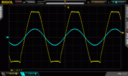
Oh sure. A careful build one doesn't oscillate, it just shows some recovery delay after clipping. Important point here is to use high quality decoupling caps as close as possible to the supply pins of the LM, as stated in the data sheet. Usually 100nF ceramic or pp will do. And modern polymer electrolytics should do as well. Attached a pic of 10kHz into a 8 ohms resistor with 100nF C0G // 22uF polymer psu bypass caps. No extra compensation caps and zobel used here.
Attachments
Linkwitz didn't hesitate to use the 3886 bridged to get around 100 watts for the woofer in his bi-amp'd Pluto speaker system. 100watts per channel is enough for any party I would ever have. If you're talking about a club or bar party, you might want to bi or triamp. Personally I use it for my midrange and tweeter (50Wrms per driver), and have an old Hafler DH220 giving 120 watts rms to each woofer. My system is triamp'd.Indeed, I have driven many kinds of speakers with the LM3886 and it rarely falls short at even severe listening levels (SPL 90dB average). It is however not a party amp 😀
Referring to another statement above, I once did an experiment where I hooked an amp up to a 6 X 9 inch speaker driver, un-baffled, just sitting there on a table, and set a sinewave generator to 3kHZ, and adjusted the volume to where we could barely stand it. To where it started to hurt to listen to it. Then we measured the voltage, did the math and found that it was 3 watts. 3kHZ is one of the most difficult frequencies to listen to by itself as a pure sustained tone. But it gave us a reference. In college I was very happy with only 25 watts rms per channel into typical efficiency Hi-Fi speakers (about 88dB spl), but it was a small room.
The thing I really like about the 3886 is that it puts out no transient at all during turn on or turn off, so it's safe to hook directly to a tweeter in a system that uses an active crossover, and that the bias of the output devices is tracked particularly well since the thermal sensors are on the same die as the output devices, so crossover distortion can be kept very minimal.


Linkwitz didn't hesitate to use the 3886 bridged to get around 100 watts for the woofer in his bi-amp'd Pluto speaker system.
Works reasonably well with 8 Ω woofers. The LM3886 doesn't have enough output current to drive a 4 Ω load in a bridge configuration.
Referring to another statement above, I once did an experiment where I hooked an amp up to a 6 X 9 inch speaker driver, un-baffled, just sitting there on a table, and set a sinewave generator to 3kHZ, and adjusted the volume to where we could barely stand it. To where it started to hurt to listen to it. Then we measured the voltage, did the math and found that it was 3 watts. 3kHZ is one of the most difficult frequencies to listen to by itself as a pure sustained tone.
3 kHz is where the ear is the most sensitive. Consulting the Fletcher-Munson curves, you can deduce that you'll need somewhere around 30-90 W to achieve the same perceived loudness within the rest of the audio band.
Tom
- Status
- Not open for further replies.
- Home
- Amplifiers
- Chip Amps
- LM3886: the effect of the compensation network Cc, Rf2 and Cf