Do you have an ebay store please?
There is no ebay and paypal in Serbia,
Regards
I have tried these parts doesn't work for me:
D1 1N4007
D2 ZFC15v
for caps 220nf I have 270nf/100v
for caps 1uf I have WMA/100v
and consider LM chip in your picture also I have one without metal back just IC in black
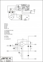
anyway at your diagram in post 1 you put D1 to the right at your picture you put it to the left opposite side, and the resistor are different.
my question is what I could replace for parts cause not all available here, and does diode here effect the general diagram or just for protection as you post?
as I can notice the data sheet for LM have also different parts,and I'm really confused.
D1 1N4007
D2 ZFC15v
for caps 220nf I have 270nf/100v
for caps 1uf I have WMA/100v
and consider LM chip in your picture also I have one without metal back just IC in black
anyway at your diagram in post 1 you put D1 to the right at your picture you put it to the left opposite side, and the resistor are different.
my question is what I could replace for parts cause not all available here, and does diode here effect the general diagram or just for protection as you post?
as I can notice the data sheet for LM have also different parts,and I'm really confused.
I have tried these parts doesn't work for me:
D1 1N4007
D2 ZFC15v
for caps 220nf I have 270nf/100v
for caps 1uf I have WMA/100v
and consider LM chip in your picture also I have one without metal back just IC in black
anyway at your diagram in post 1 you put D1 to the right at your picture you put it to the left opposite side, and the resistor are different.
my question is what I could replace for parts cause not all available here, and does diode here effect the general diagram or just for protection as you post?
as I can notice the data sheet for LM have also different parts,and I'm really confused.
This is correct schematic and layout,
Regards
Attachments
The file is not legible. Could you post it a bit larger please?
Uriah
Did you click on it to make it larger?
The expand point may not be so obvious on this image.
In the bottom left corner after clicking on the image there is a square made up of arrows if you click here Uriah then it will expand to full size 🙂
edit: note you need to move the mouse over the image for the expand arrows to appear too! (at least in firefox and IE).
Tony.
In the bottom left corner after clicking on the image there is a square made up of arrows if you click here Uriah then it will expand to full size 🙂
edit: note you need to move the mouse over the image for the expand arrows to appear too! (at least in firefox and IE).
Tony.
Attachments

Last edited:
Any chance there is a DWG file available for the PCB and PSU (comp and solder sides)? I have access to a benchtop CNC and would like to try to mill a PCB.
Anyone have experience with that? Words of warning?
Peace.
Anyone have experience with that? Words of warning?
Peace.
I dont have one but I have a suggestion.
I use this software and it is extremely easy to learn to use. Literally minutes and you will draw your first line. Everything is self explanatory. Obviously I am very pleased with it. It does output HPGL which is what you need I think.
Sprint-Layout
Its called Layout50 and its 40Euro. Its costing a little more every year or so. I think I paid about 50USD for it several years ago. Anyway, its worth it to me and you could whip up a board for this in an hour or so as long as you had all the component footprints already. You would have to build a footprint for LM3886 but thats real easy when you have the datasheet to help you.
Hope its not to off topic. Just a great program for guys like us.
Uriah
Uriah, thanks for the idea. Software is not my issue. I have AutoCAD Inventor and software to program a CNC available through work. The CNC software will open DXF files which I can generate from DWG.
Now, as I am a relative newbie to all that software: can someone advise how to turn a PDF/JPEG into a DWG through an import? Sorry for slightly OT.
Now, as I am a relative newbie to all that software: can someone advise how to turn a PDF/JPEG into a DWG through an import? Sorry for slightly OT.
Last edited:
If you are asking how to convert PDF/JPEG to DWG (AutoCAD), it is not practical. JPEG files contain information on the images/colors/compression etc, while DWG files contain information on the lines, circles, arcs etc that compose the AutoCAD drawing. Even if some software were to provide you this ability, it is will be half baked, requiring a lot of rework or errors. Best to to create the drawing all over.
Din...thanks. I have tried a couple packages that convert to DXF, but as you say: less than acceptable results. Back to the drawing board...
Electrical drowing!
Hello!
Give me (Show) the power supply electrical drowing for Amplifier with LM3886.
Thank you advanced 😉
Hi jerryo,
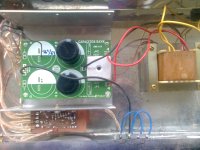
This is for you
Hello!
Give me (Show) the power supply electrical drowing for Amplifier with LM3886.
Thank you advanced 😉
Last edited:
Now, as I am a relative newbie to all that software: can someone advise how to turn a PDF/JPEG into a DWG through an import? Sorry for slightly OT.
Sorry for the late reply. For PCB milling, we don't normally go the
DWG/DXF route, but directly to gcode.
If you use Eagle to do your PCB, then there's pcbgcode.
PCB-GCode Phorum
PCB Isolation Routing
PCB Milling - RepRapWiki
For gerber to gcode -
Cynbe's PCB Milling Gerber to G-code converter
PCB to Gcode | Download PCB to Gcode software for free at SourceForge.net
G-code processing [+gerber file processing! ?]
Very small PCB based on Yorkville Amps.
For the size of the PCB lay out how much mr?
Very small PCB based on Yorkville Amps.
what is the size of the PCB???
Post #7
sorry less thorough in reading???😀😀😀 if the top layer can be displayed mr?
- Home
- Amplifiers
- Chip Amps
- LM3886 Schematics + PCB