No PSRR measurements tonight. Sorry guys. To modulate the supply, I need an amp that can deliver enough current to drive the LM3886 and can drive the supply capacitance (hopefully, I can take the 1000 uF off). The amp also needs to be DC coupled. I had such an amp, but I took it apart to use the LM3886es in it for my P2P vs PCB experiment. Grr...
I'll get there eventually. It's not a real high priority right now.
~Tom
I'll get there eventually. It's not a real high priority right now.
~Tom
I was chained up to a HP8566 (Cadillac of the day) in a screen room for years.
I occasionally find myself chained to the Agilent E5052B in the screen room at work. I think the new price on those is about what my house is worth... But if you need to measure phase noise with a -175 dBc noise floor, that's the ticket.
~Tom
You don't like it? Most of the designs here at Diyaudio use this method of speaker return (grounding), including the great My_Ref_c.
No, I don't like it, it's dead wrong...I could show you (and others) a pcb done right from the members here like this one SymAsym5 - Project
or something even better for a chip amp like LM3886...see http://www.diyaudio.com/forums/chip-amps/226437-optimizing-tda7294-output-15.html#post3312141
Hi Tony that looks pretty nice. what software are you running? I guess getting some measurement software is key, which then determines the interface hardware / sound card requirements. yes I think balanced interfaces are necessary will look into that some more
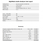
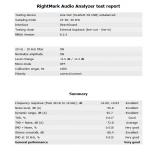
yes Tom was right. Holmimpulse and ARTA. I just used ARTA in free mode. I've also tried audiotester (in trial mode) and it seems very good. I do use RMAA as well. RMAA sumary for balanced and unbalanced mode attached. I think if I can make a decent balanced to unbalanced converter I will be able to use it quite effectively for amp testing 🙂 I'm unsure why the THD+N on the balanced is a bit low, some more experimenting probably needed.
Tony.
Attachments
Last edited:
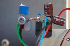
OK after going back over the posts again, It is starting to make more sense 🙂 Tom, Mark and aparatusonitus I think I get it now. Making any changes to this chipamp is going to be difficult because of the tight construction, but I could probably link the various points back to the decoupling caps common point (pic attached) and then run from their back to the PS. This would seem to be the most sensible approach based on everyone input (and the limitations of my build). I would probably (at least initially) leave the speaker returns where they are as that will be more difficult to manage, but I could probably manage to put them back to the decoupling caps star point as well. Something feels wrong about that but I get the point about loop area 🙂 Perhaps a short length from the star point to a second star with just the speaker return, and then the long haul back to the PS...
Picture attached with star point arrowed. Unfortunately not likely to get any attention any time soon (and I would like to have decent measuring capability before I embark on any changes so I can do before and after comparisons) but I will look at this at some point 🙂
Tony.
Picture attached with star point arrowed. Unfortunately not likely to get any attention any time soon (and I would like to have decent measuring capability before I embark on any changes so I can do before and after comparisons) but I will look at this at some point 🙂
Tony.
Attachments

Move red wimas HF decoupling caps as close as possible to chip psu pins, the other ends of wimas form the amp power ground point where your signal (input, feedback) have to be referenced via separated wire. Don't make a power ground point a big surface area, it should be a point!
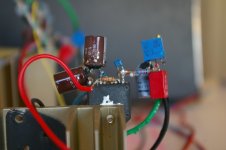
The 2 EURO GAINCLONE.
Not exactly to my schematic, you can see the speaker return and PSU return connected to the caps. this is the star 0V (ground). Its been rebuild a few times.
Not exactly to my schematic, you can see the speaker return and PSU return connected to the caps. this is the star 0V (ground). Its been rebuild a few times.
Attachments
Last edited:
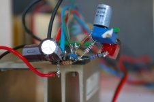
Um... This is obviously a prototype, not the final circuit, but in order for that heat sink to do anything at all, the back of the entire IC package needs to make good thermal contact.
Just saying... Thermals are important with the LM3886.
~Tom
Just saying... Thermals are important with the LM3886.
~Tom
2 Mark & Tony,
If you haven't already done so, input and feedback resistors/capacitors network must be as close as possible to -In/+In pins. Also, use a non-inductive, 1W resistor for the Rf feedback resistor, gain seting resistor Rg can be of 1/4W power rating.
If you haven't already done so, input and feedback resistors/capacitors network must be as close as possible to -In/+In pins. Also, use a non-inductive, 1W resistor for the Rf feedback resistor, gain seting resistor Rg can be of 1/4W power rating.
Even with 42 V rails, there's no need for a 1 W feedback resistor - unless you go really low on the feedback impedances.
Rf = 10 kOhm would give you 90 mW of power dissipation for rail-to-rail operation using +/-42 V rails. A 250 mW rated or 0.4~0.5 W resistor would work just fine. The thermals on the LM3886 would be a much, much bigger challenge than those on the resistor.
The critical part in the feedback network is the inductance from Vout to IN(-). I demonstrated that quite clearly in This Thread (Post #66). That's also mentioned in the datasheet. The parasitic inductance from IN(-) to ground through the outher resistor is less critical. Inductance between Vout and the feedback tap-off point sets up a complex pole pair (bad news for stability) with the load capacitance, hence, the output parasitics need to be minimized. Basically, Lout and Cload gives you a second order LC filter "for free".
~Tom
Last edited:
Hi Tom,
It about noise generated in Rf...high power one will have lower noise. Have to go to bed now...
It about noise generated in Rf...high power one will have lower noise. Have to go to bed now...
Um... This is obviously a prototype, not the final circuit, but in order for that heat sink to do anything at all, the back of the entire IC package needs to make good thermal contact.
Just saying... Thermals are important with the LM3886.
~Tom
Yes, only a prototype to test different layouts.
If you have a low parasitic feedback loop and a good PSU design, it hardly gets warm. I have some copper heatsinks from a 10 kW power supply for the final build.
Last edited:
It about noise generated in Rf...high power one will have lower noise. Have to go to bed now...
I'm guessing you're referring to excess noise.
A recap: Noise types in a resistor.
Thermal noise: Thermal noise is all determined by physics. Electrons jump around randomly. This creates white noise with a noise spectral density of En^2 = 4*k*T*R. k is Bolzman's constant (1.38E-23 J/K), T is the absolute temperature (deg K), R is the resistance in ohm. En^2 is the noise spectral density (~power)
in V^2/Hz.
1/f (aka flicker or popcorn) noise in passives is really a thing of the past due to the use of carbon composite resistors. CC resistors were made by jamming a bunch of carbon together in a tube and sticking a wire at each end. The flow of electrons near the boundaries of the carbon clumps is not random in time, hence, the noise spectrum has an 1/f component. Carbon film and metal film resistors do not exhibit 1/f noise.
If you measure a real resistor, you'll find a little bit of extra noise that cannot be explained by thermal noise or 1/f noise. This is called excess noise. Carbon film and metal oxide resistors both have relatively high excess noise. It is true that carbon film resistors rated at higher power will exhibit less excess noise than one rated for lower power, but the difference between a 0.25 W and a 2 W CF resistor is only about 2x.
The best way to get rid of the excess noise is to use metal film resistors. Changing from carbon film resistors to metal film ones will lower the excess noise by over 40 dB in some cases. Versus the 6 dB improvement you'd get by switching to 2 W resistors from 0.25 W.
Source: Douglas Self, "Small Signal Audio Design".
~Tom
If you measure a real resistor, you'll find a little bit of extra noise that cannot be explained by thermal noise or 1/f noise. This is called excess noise. Carbon film and metal oxide resistors both have relatively high excess noise. It is true that carbon film resistors rated at higher power will exhibit less excess noise than one rated for lower power, but the difference between a 0.25 W and a 2 W CF resistor is only about 2x.
Thanks for an elaborated replay Tom...so if we are in agreement that we will have some excess noise added by Rf resistor, the big question is what will an amp do with it? Is it going to be rejected by amp's CMRR (some, none), whether it will be amplified by the amp loop gain (by multiplication) or simply added to the amp output (by addition)?
Thanks for an elaborated replay Tom...so if we are in agreement that we will have some excess noise added by Rf resistor, the big question is what will an amp do with it? Is it going to be rejected by amp's CMRR (some, none), whether it will be amplified by the amp loop gain (by multiplication) or simply added to the amp output (by addition)?
If you use a metal film or wire wound resistor, then there won't be any excess noise to worry about. WW resistors are considered excess noise free and metal film have 10 nV/V of excess noise. The input voltage noise, for example, is 2.0 uV (TYP) 10 uV (worst case). Compare that with the 180 nV you'd get in excess noise from the metal film feedback resistor. Noise sums as powers. So the total noise in the typical case will be sqrt((180E-9)^2 + (2E-6)^2) = 2.008 uV. Seriously! Don't worry about it.
The CMRR will do nothing to error signals applied to Rf. The signal isn't common-mode; it's differential mode.
Unfortunately, the input current noise is not specified for the LM3886, so it's anybody's guess what the output noise will be.
~Tom
Last edited:
Noise sums as powers.
The CMRR will do nothing to error signals applied to Rf. The signal isn't common-mode; it's differential mode.
I stll don't get it...in the first quote you say noise will be added at the output, right?
In the second quote you said error signal (noise) is differential mode, if so is it be amplified by the input LTP gain?
I got into the details of layout and component choice to increase stability this should be the number one design goal. How can the audio sound good if the amp is unstable and oscillating. Maybe look at closed loop gain and phase next?
Resistor noise due to materials are mostly concerns for high gain preamps and are very likely swamped out by higher than average current noise in a monolithic analog power device. Tom was an op-amp designer at TI so he could probably make a rough estimate based on a high voltage Si bjt processes, note: data sheet recommends low value gain setting and bias values anyway so that is another clue of input noise current.
Last edited:
Resistor noise due to materials are mostly concerns for high gain preamps and are very likely swamped out by higher than average current noise in a monolithic analog power device.
Exactly. It's all a matter of which noise source is dominant. If the #2 noise source is 4~5 dB down, it actually doesn't impact the overall noise in any significant way. Nail the loudest contributor. Do your best on the others, but there's no point in going after contributors far down the list. Of course the distribution changes as you reduce the dominant source, so you go through this optimization loop until everybody is about equally loud. Then you're done. This assumes that you have full control over everything - as you (almost) do in an IC design process. In case of the LM3886, you just have to make everything quieter than the LM3886. That's not hard.
Tom was an op-amp designer at TI so he could probably make a rough estimate based on a high voltage Si bjt processes, note: data sheet recommends low value gain setting and bias values anyway so that is another clue of input noise current.
I actually still design op-amps. Just not the kind you buy in the store. My amps are typically parts of larger subsystems inside our precision timing chips. I like the precision work. Ultra-quiet voltage regulators with a prescribed temperature coefficient (very different from zero, may I add) and that sort of stuff. My resume is on my website if anybody is curious about my background.
The LM3886 is old enough that I'm not familiar with the process it's on. It's obviously a bipolar or BiCMOS process, but aside from that I don't know the details. You can probably make some educated guesses about the noise voltage and currents by comparing with similar products of the era, but in the end, you're better off just measuring them yourself. That can be a bit tricky, but I'd think you can do that with a sound card as well. Or a true RMS voltmeter with a decent bandwidth (so probably a bench top model rather than a handheld).
While on the topic of op-amps. By far the best book I have ever found on how to use op-amps, their limitations (both DC and AC), noise, stability, etc. is Sergio Franco, "Design with Operational Amplifiers and Analog Integrated Circuits", 3rd Edition. ISBN: 0072320842. It's bloody expensive but worth every penny. It's a pretty easy read, actually. Not the usual engineering textbook "ooh, look at me and how I dazzle you with my fancy equations". It is a textbook, though. Not a cookbook. I have both the 2nd and 3rd editions. Either one would work, but the 2nd might be available used for a lot less.
~Tom
Last edited:
I got into the details of layout and component choice to increase stability this should be the number one design goal. How can the audio sound good if the amp is unstable and oscillating. Maybe look at closed loop gain and phase next?
Well... If the amp is oscillating, you'll probably fry your speakers.
There is a definite tradeoff between phase margin, bandwidth, and overshoot on the transient response. More on the latter here: Overshoot vs PM (2nd order systems). The question is then how much OS is acceptable. I suspect a few percent is probably OK, so a PM above 70 º is desired. Some people say you need at least 85 º, but I haven't seen any data backing that up.
Measuring the closed loop response tells you very little about the PM. You need to measure the loop gain (i.e. amplifier open loop * feedback gain). I plan to do that next. I'm still waiting for my new toy to arrive.
~Tom
- Home
- Amplifiers
- Chip Amps
- LM3886 PCB vs Point-to-Point (with data)