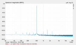
-180º and +180º are indistinguishable without knowledge of the absolute timing of the input. What you're seeing is a software issue. The software isn't smart enough to figure this out. It's also possible that noise in the measurement, possibly the mains hum, is throwing the phase measurement off.There are two strange occurrences where the phase shifts from -180 to 180 deg in the frequency range from 300 Hz to 3000 Hz and second region from 7kHz to 8kHz.
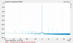
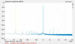
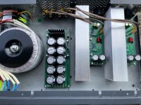
All the 'grass' in the FFT plots is mains related. Your chassis layout looks pretty good, so I'm a bit surprised of this. I'd probably shorten up the wires on the transformer secondary and bundle them tightly, but I doubt that'll make a big difference.
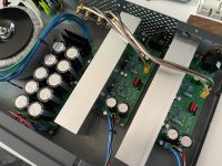
Have you looked at left vs right channel in the chassis. If the channel that's further away from the transformer is significantly better than the channel in the middle of the chassis you're looking at interaction with the transformer and/or rectifier. If the difference between the two channels is small, I bet you're looking at a grounding issue. Do you have XLR Pin 1 grounded to the chassis?
Tom

XLR pin 1 connected to the ground on PCB. GND signal is coming from the power supply board to the amp board. GND is formed by two middle wires from the transformer.
I realized that GND from transformer secondary windings is not connected to the chassis. Only mains GND is connected to the chassis
I realized that GND from transformer secondary windings is not connected to the chassis. Only mains GND is connected to the chassis
... or more complicated. There's a lot to amp design that's solved for you in the LM3886.I could go with a discrete design and that would get me more power - 100W to 300W. Probably would be simpler (or more tunable, customizable).
Good thoughts. Curious folks can read more here: https://neurochrome.com/pages/output-powerThoughts behind the above solution:
Bridging two LM3886 limits output current. Cannot work with 4ohm loads.
Paralleling two LM3886 doubles the current. Better load capability. Using them both in inverted mode decreases common mode distortion (slightly).
Tom
Your two statements about how the transformer is (or isn't) grounded seem to be contradictory. Schematic?XLR pin 1 connected to the ground on PCB. GND signal is coming from the power supply board to the amp board. GND is formed by two middle wires from the transformer.
I realized that GND from transformer secondary windings is not connected to the chassis. Only mains GND is connected to the chassis
XLR pin 1 should also connect to the chassis. Often XLR connectors will have a pin or tab for this.
Tom
Looks like I need to ground pin 1 and try measuring again.Your two statements about how the transformer is (or isn't) grounded seem to be contradictory. Schematic?
XLR pin 1 should also connect to the chassis. Often XLR connectors will have a pin or tab for this.
Tom
Is linear non regulated power supply able to deliver clean power in general? I’m wondering if this is something I can fix (ground layout maybe) or this is limitation of the topology in itself?
I am thinking maybe using switching power supply from Connex (smps300re) will give cleaner power?
Or maybe use regulators like LM338 (two of them per rail to share the current) will remove that “grass” from the graph
Thank you for your help and support!-180º and +180º are indistinguishable without knowledge of the absolute timing of the input. What you're seeing is a software issue. The software isn't smart enough to figure this out. It's also possible that noise in the measurement, possibly the mains hum, is throwing the phase measurement off.
All the 'grass' in the FFT plots is mains related. Your chassis layout looks pretty good, so I'm a bit surprised of this. I'd probably shorten up the wires on the transformer secondary and bundle them tightly, but I doubt that'll make a big difference.
Have you looked at left vs right channel in the chassis. If the channel that's further away from the transformer is significantly better than the channel in the middle of the chassis you're looking at interaction with the transformer and/or rectifier. If the difference between the two channels is small, I bet you're looking at a grounding issue. Do you have XLR Pin 1 grounded to the chassis?
Tom
And btw Merry Christmas and happy holidays! 😁🎄
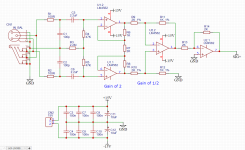
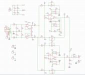
Had some time on my hands, so revisited schematics. Simplified servo and moved coupling capacitor to the input - now it is only 2.2uF which allows to use film type. Used remaining half of the OPAMP to invert the signal back to 0deg at output. V+ now has bigger PCB trace/pour.
Apparently film capacitor has less THD according to this - https://www.ti.com/lit/pdf/slyt796
Apparently film capacitor has less THD according to this - https://www.ti.com/lit/pdf/slyt796
Attachments

Measures much better than the previous build.
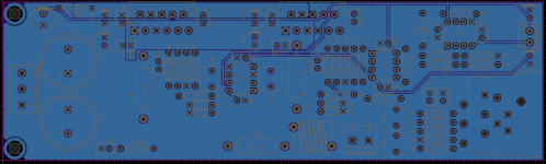
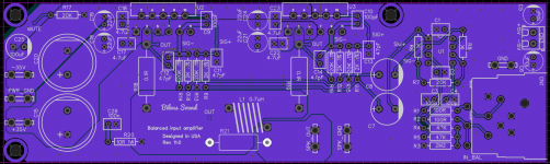
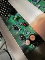
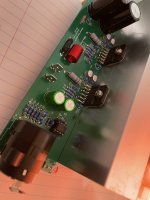
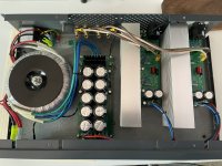
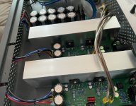
Also attached is the picture of the case layout.
Also attached is the picture of the case layout.
Attachments
-
 channel1-smaller offset - mes2.png311.1 KB · Views: 173
 -
 channel2 - bigger offset - closer to psu - vout 20v - cursor 60hz.png445.5 KB · Views: 160
 -
 channel2 - bigger offset - closer to psu - vout 20v - cursor 3000hz.png426.1 KB · Views: 176
 -
 7AB0C628-B5C7-46A6-A513-589704404387.jpeg550.6 KB · Views: 177
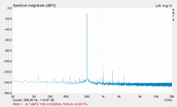
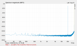
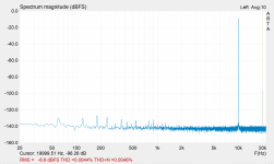
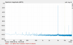
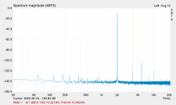
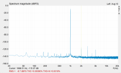
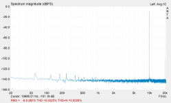
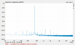
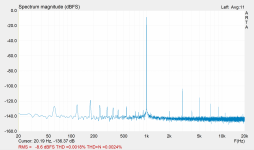
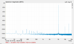
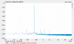
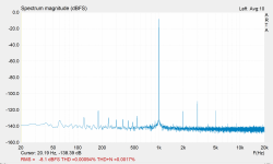
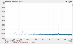
Reconfigured gain and here are the new measurement results.
Now, the first opamp which is JFET OPA2134 has more amplification, while LM3886 is less. The difference in sound is significant. It also shows in measurements - where the second harmonic is more in line with the third - comparing to the before result where the third and next odd harmonics where more prevalent.
Now, the first opamp which is JFET OPA2134 has more amplification, while LM3886 is less. The difference in sound is significant. It also shows in measurements - where the second harmonic is more in line with the third - comparing to the before result where the third and next odd harmonics where more prevalent.
Attachments
-
 channel1-smaller offset - 1000hz -new-gain-setting.PNG392.4 KB · Views: 108
 -
 channel1-smaller offset - 500hz -new-gain-setting-18.48V out.PNG434.6 KB · Views: 110
 -
 channel1-smaller offset - 20_000hz -new-gain-setting-18.48V out.PNG448.7 KB · Views: 116
 -
 channel1-smaller offset - 10_000hz -new-gain-setting-18.48V out.PNG445.9 KB · Views: 106
 -
 channel1-smaller offset - 5_000hz -new-gain-setting-18.48V out.PNG354.4 KB · Views: 109
 -
 channel1-smaller offset - 2_000hz -new-gain-setting-18.48V out.PNG427.6 KB · Views: 107
 -
 channel1-smaller offset - 1000hz -new-gain-setting-18.48V out - warmed up chips.PNG424.8 KB · Views: 100
 -
 channel1-smaller offset - 1000hz -new-gain-setting-18.48V out.PNG337.4 KB · Views: 103
 -
 channel2-bigger offset - 1000hz -new-gain-setting-18.4V out.PNG329.6 KB · Views: 104
 -
 channel2-closer to psu - 10_000hz -new-gain-setting-18.4V out.PNG357.3 KB · Views: 110
 -
 channel2-closer to psu - 500hz -new-gain-setting-18.4V out.PNG351.5 KB · Views: 117
LM3886 parallel amp measurements
Rload = 8 ohms
Channel 1
smaller offset
Max output: 18.4V AC
Input level for max output: 0.856V AC
THD @ 1kHz: 0.00076%
THD+N @ 1kHz: 0.0018%
THD @ 10kHz: 0.0044%
THD+N @ 10kHz: 0.0046%
THD @ 0.5kHz: 0.00054%
THD+N @ 0.5kHz: 0.0017%
Channel 2
bigger offset / closer to PSU
Max output: 18.4V AC
Input level for max output: 0.856V AC
THD @ 1kHz: 0.00079%
THD+N @ 1kHz: 0.0018%
THD @ 10kHz: 0.0025%
THD+N @ 10kHz: 0.0028%
THD @ 0.5kHz: 0.00053%
THD+N @ 0.5kHz: 0.0018%
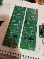
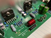
And with this post attached are more pictures of the build.
Rload = 8 ohms
Channel 1
smaller offset
Max output: 18.4V AC
Input level for max output: 0.856V AC
THD @ 1kHz: 0.00076%
THD+N @ 1kHz: 0.0018%
THD @ 10kHz: 0.0044%
THD+N @ 10kHz: 0.0046%
THD @ 0.5kHz: 0.00054%
THD+N @ 0.5kHz: 0.0017%
Channel 2
bigger offset / closer to PSU
Max output: 18.4V AC
Input level for max output: 0.856V AC
THD @ 1kHz: 0.00079%
THD+N @ 1kHz: 0.0018%
THD @ 10kHz: 0.0025%
THD+N @ 10kHz: 0.0028%
THD @ 0.5kHz: 0.00053%
THD+N @ 0.5kHz: 0.0018%
And with this post attached are more pictures of the build.
Attachments

I made a mistake when measuring power output. I generated 1kHz tone and measured that with my Fluke. Apparently I had to generate 400Hz as it is the highest frequency Fluke can measure accurately.
New
Max output: 18.93V AC
Input level for max output: 0.865V AC
Pout = 18.93V * 18.93V / 8ohm = 44.79 W rms
Should I get more power output by paralleling two chips? Should it be 65W into 8ohm?
DC voltage at full power output drops to 33.8V
My transformer voltage drops from 26.4V ac to 26.1V ac
I am using PB3510 rectifier bridge by Vishay,
could this be a problem?
Should it give 26V *1.41 = 36.66V dc out?
the "problem" is that any rectifier will reduce the voltage (usually 2 x diode drop voltage).could this be a problem?
you cannot avoid this (unless you use active MOS-FET rectifiers).
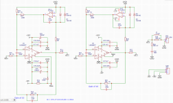
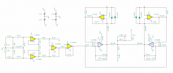
So here is pretty much final version:
View attachment 1031999
How ironic is this post from almost a year ago? I was too naive to think that I had “final revision” back then. 🤷🏻♂️😂
At this point I am quite happy with the amplifier that I have built as a result of my journey into electrical engineering topics of sound amplification. Thank you everyone who contributed on this forum! as without you I would have not been where I am now. The engineering community on this forum is truly great and everyone is genuinely interested and helpful!
Here is the brief summary of the last year:
I am attaching the schematics to the amplifier as I have it right now. Also attached are the THD+N screenshots.
At 4 ohms the amp produces 19.5V AC on its output measured @ 400Hz sine wave. Doing math shows output power at 95.06W.
At 8 ohms the voltage out was 20.13V AC. Doing math shows output power at 50.65W.
Power is provided by unregulated linear power supply and the voltage at full power out is 33.8V DC.
Here is the brief summary of the last year:
- I learned EasyEDA editor and made countless designs of different PCBs for different circuits.
- I learned LTSpice simulator, imported external models, and was able to analyze DC, AC, and transfer characteristics for various circuits.
- I then migrated to use TINA TI simulator and relearned everything from LTSpice.
- I have soldered countless prototypes.
- I have learned how to use ARTA to measure THD+N using my audio interface.
- I also acquired small and cheap oscilloscope and learned how to use it to see if amplifier is clipping nicely and if it oscillates.
- After many prototypes of two paralleled LM3886 I have built the one with the servo, but unfortunately it did not show very good THD+N performance.
- I tore it down and built simplified solution with ballast resistors and it turned out great! THD+N is very good.
I am attaching the schematics to the amplifier as I have it right now. Also attached are the THD+N screenshots.
At 4 ohms the amp produces 19.5V AC on its output measured @ 400Hz sine wave. Doing math shows output power at 95.06W.
At 8 ohms the voltage out was 20.13V AC. Doing math shows output power at 50.65W.
Power is provided by unregulated linear power supply and the voltage at full power out is 33.8V DC.
Attachments
-
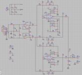 sch.png57.6 KB · Views: 244
 -
 ch2_4ohm_0.4kHz_OPA2134.PNG446 KB · Views: 217
 -
 ch2_4ohm_1kHz_OPA2134.PNG189.1 KB · Views: 138
 -
 ch2_4ohm_5kHz_OPA2134.PNG382 KB · Views: 131
 -
 ch2_8ohm_OPA2134_0.4kHz.PNG439.9 KB · Views: 127
 -
 ch2_8ohm_OPA2134_1kHz.PNG397.4 KB · Views: 124
 -
 ch2_8ohm_OPA2134_5kHz.PNG467 KB · Views: 135
 -
 61F69987-E9FE-434E-B94F-93C17B3F3E49.jpeg522.1 KB · Views: 145
 -
 3C306CA3-205E-4D8A-B9BD-4E29D530F36A.jpeg504.6 KB · Views: 214
Last edited:
- Home
- Amplifiers
- Chip Amps
- LM3886 in parallel with servo circuit build attempt