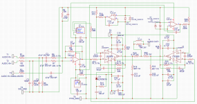
This might get you interested (and started) in simulation. This file should just click and run in LTpsice and uses opamps in place of the LM3886. The gain structure is the same.
Click my signature line to see how to get started.
View attachment 1030827
I already loaded this file and I was surprised that all the hard work was already done! That file is just an exact schematics ready to be run! Thank you so much!
I just need to load the LM3886 module into it somehow. Will dig into the tutorials.

Attachments

I just need to load the LM3886 module into it somehow. Will dig into the tutorials.
Models are the thing I struggle the most with and I still find them hugely frustrating. See how you get on 🙂
Opamps I am considering:
For signal path:
NE5532 - $1.32
Vos (input offset voltage) - 4mV, Ib (input bias current) - 800nA
LM4562 - $2.42
Vos - 0.7mV, Ib - 72nA
LME49720 - $3.41
Vos - 0.7mV, Ib - 72nA
OPA2134 - $6.15
Vos - 2mV, Ib - 100pA
For servo circuit:
TL072BCP - $1.93
Vos - 3mV, Ib - 200pA
OPA2277PA - $6.34
Vos - 35uV, Ib - 4nA
Last edited:

I would be quite happy with a TL072 as a servo. The output offset is typically going to be in the couple of millivolts region using one of those.
You can't go far wrong with an NE5532 as a linear amp although the LM4562 is possibly a better option on paper. Given a choice I'd go the LM4562,
You can't go far wrong with an NE5532 as a linear amp although the LM4562 is possibly a better option on paper. Given a choice I'd go the LM4562,
Updated resistors R13 and R28 to 1K. According to AN-1192 they should match resistance of Ri (R12, R29).
On the same note, R14 and R27 should be 10 times of R16 and R25 (feedback resistor) respectively.
It probably makes no difference in practice simply because you have a DC servo to correct any offsets. When the amp is built for real then ideally you want a value of resistor that gives 0.00 volts DC at the output of the servo opamps. In the simulation the DC voltage is around 1.2 volts with a 2k2 and half that with a 1k. Remember you have up to -/+ whatever the opamp supply is as a correction voltage and so its a non issue.
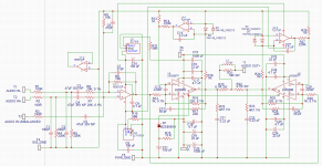
Here is 2k2 and 1k

Since I am using only half of the two opamps that come in the DIP-8 package - what should I do with the other half? Just leave in unplugged? Was hoping to make separate PCB for each channel.
Board layout depending you would use all of them wouldn't you?
If you want to use just one from each then use TL071 single opamp and... what's the single version of the LM4562?... or if you leave any unused then you tie the + non inverting input to ground and connect output to - (inverting) input so its configured as a buffer.
If you want to use just one from each then use TL071 single opamp and... what's the single version of the LM4562?... or if you leave any unused then you tie the + non inverting input to ground and connect output to - (inverting) input so its configured as a buffer.
That'll work.
The OPA2202 that Tom mentioned looks nice for a servo and isn't particularly expensive ($1.73). It's SMD only, but SOIC packages are extremely easy to solder, in my opinion. With a slight modification to your circuit, you'd get absolute wort-case DC offset of <1mV and typical of 45µV. The OPA2202's bias current isn't incredibly low (250pA typ), but its offset current is only 25pA (typ). If the DC source resistance to the + and - pins is equal, the error from the bias current goes away, leaving only the error from the offset current and offset voltage. Adding a 1M resistor between the + pin and ground (with a capacitor across it to short out the noise) will accomplish this.For servo circuit:
TL072BCP - $1.93
Vos - 3mV, Ib - 200pA
OPA2277PA - $6.34
Vos - 35uV, Ib - 4nA
Like this?
Yes. Or if easier for a board layout you can take the + input to the output of the opamp in use.
The servo really is a non problem imo when talking of offsets and there are many suitable opamps.
True that. Do beware that the servo can impact the audio performance of your circuit towards the low end of the audible spectrum. You may need to push the pole of the DC servo well into the mHz range to prevent it from contributing significantly to the THD at 20 Hz. Or.... Use a servo with a steeper filter slope.
Tom
Tom
- Home
- Amplifiers
- Chip Amps
- LM3886 in parallel with servo circuit build attempt