The PCB layout has some problems. The ground layout looks something like this:
Power->Output->Input->R5->C25->C26->C6->pin7->C1->C2
The power rails are not any better. Power connects to the chip pins and then connects to the capacitors.
Can anyone see how we can improve the ground layout without cutting traces?
Power->Output->Input->R5->C25->C26->C6->pin7->C1->C2
The power rails are not any better. Power connects to the chip pins and then connects to the capacitors.
Can anyone see how we can improve the ground layout without cutting traces?
Hi,
Well, that's means that I have been 3 times lucky. Like I said it is worked for me and I will recommended it as a reference to any one with hum problems. Any way this is not about my ground wiring. Now, lets try to concentrate and fix morky hum problem. Lets wait for the AC voltage reading.
You may have to wait a while. He said a few posts back that his voltmeter can't resolve voltages that low.
Tom
That's exactly the case. Unfortunately my voltmeter can't see voltages(AC) that low (DC is fine). Is there something else I can do until I borrow one that can see voltages that low?
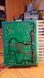
The PCB layout has some problems. The ground layout looks something like this:
Power->Output->Input->R5->C25->C26->C6->pin7->C1->C2
The power rails are not any better. Power connects to the chip pins and then connects to the capacitors.
Can anyone see how we can improve the ground layout without cutting traces?
can you explain that further?
There are charging currents to and from the capacitors (Power GND->C26 and Power GND->C1). These are passing though the same traces as the input ground (Input->R5->pin7->?). This could be the cause of the hum.
One must never take the audio circuits to the PSU charging circuit. NEVER !
Resolve the charging side as a compact low loop area layout that minimises the radiated interference.
Then take the PSU power out as a twisted pair/triplet to the power input of the receiver.
Resolve the charging side as a compact low loop area layout that minimises the radiated interference.
Then take the PSU power out as a twisted pair/triplet to the power input of the receiver.
Hi,
You can remove the bridge from the board and mounting it outside the board. Use the one that you can mount it in the chassis. I never like to mount the bridge on the amplifier board. The best it is to mount it outside and then bring the dc filter voltage to the board.
You can remove the bridge from the board and mounting it outside the board. Use the one that you can mount it in the chassis. I never like to mount the bridge on the amplifier board. The best it is to mount it outside and then bring the dc filter voltage to the board.
Buy an X-Y Kit
I know you've invested some time in this amp, but I'd buy a complete kit (or PCB) from China. These boards are as simple to put together as pie. Beside the chip, they use about 8 passive components. And you can find them for about ~$10USD/channel. With a nice SMPS, or linear PSU, you will have a sweet sounding amp. They're stupidly simple and following standard guidelines for wiring the inputs and outputs as per Andrew it will just work - with zero hum. 🙂 As has been noted, keep the chassis isolated from everything except for the tranny 'screen' wire (if your tranny has one) and the IEC earth ground connector. I always use green wire for earth ground. Keep all signal and returns in their own domain(keep 2 wires together) ALWAYS!
I'm at work (secure) too and can't see your pictures.
Totally agree with redjr regarding trying the XY LM3886 amps.
I was thinking about making the same suggestion, but redjr beat me to it. I got 3 pairs of those Chinese XY amps, and never got any hum from them. The only change I made (could not help myself) is to solder the feedback (22K) resistor directly across the pins of the chip. They sound fine to me. I've tried various class-D amps recently, but now I have settled on using those cheap Chinese chip amps to drive my main speakers (Speaker Lab K). No audible hum, no audible noise, even if I press my ear right into the horns.
I used to build LM3875 amps (the Gainclones) using point-to-point wiring, but I don't see the point of doing that anymore, now that I have those cheap Chinese LM3886 amps. You can get 2 amp boards plus a power supply board all for $6, with free shipping!
2pcs LM3886 HiFi Power Amplifier PCB Rectifier Filter Power Supply PCB | eBay
Kurt
Totally agree with redjr regarding trying the XY LM3886 amps.
I was thinking about making the same suggestion, but redjr beat me to it. I got 3 pairs of those Chinese XY amps, and never got any hum from them. The only change I made (could not help myself) is to solder the feedback (22K) resistor directly across the pins of the chip. They sound fine to me. I've tried various class-D amps recently, but now I have settled on using those cheap Chinese chip amps to drive my main speakers (Speaker Lab K). No audible hum, no audible noise, even if I press my ear right into the horns.
I used to build LM3875 amps (the Gainclones) using point-to-point wiring, but I don't see the point of doing that anymore, now that I have those cheap Chinese LM3886 amps. You can get 2 amp boards plus a power supply board all for $6, with free shipping!
2pcs LM3886 HiFi Power Amplifier PCB Rectifier Filter Power Supply PCB | eBay
Kurt
I know you've invested some time in this amp, but I'd buy a complete kit (or PCB) from China. These boards are as simple to put together as pie. Beside the chip, they use about 8 passive components. And you can find them for about ~$10USD/channel. With a nice SMPS, or linear PSU, you will have a sweet sounding amp. They're stupidly simple and following standard guidelines for wiring the inputs and outputs as per Andrew it will just work - with zero hum. 🙂 As has been noted, keep the chassis isolated from everything except for the tranny 'screen' wire (if your tranny has one) and the IEC earth ground connector. I always use green wire for earth ground. Keep all signal and returns in their own domain(keep 2 wires together) ALWAYS!
I'm at work (secure) too and can't see your pictures.
At this point I don't really "need" the amp. I just happened to stumble upon the board after more than 5 years and figured why not. I had some speakers laying around and thought it would be a great opportunity to build an amp and learn from it. Being an electronic engineer I followed a completely different path but I guessed it would be a nice way to spend my free time. What I'm trying to say is I don't mind troubleshooting this amp as long as I'm learning from it.
Those Chinese kits are definitely a great deal but I don't see the point in getting one right now, plus it would be kind of hard to get one due to the capital controls here in Greece. I might get one after I'm completely convinced that I this amp is a complete waste of time.
Also I want to point out that when we were building this board in our lab each one of us had one. And I heard from other classmates that their board worked fine and hum-free. So it might have something to do with my soldering? How could I check that?
I found from a friend a 2x12 transformer and I'll try powering the amp with it just to eliminate the possibility that the hum is from the transformer.
Morky, if you test the amp with lower voltages you will probably need to reduce Rmute (R9+R12 and R24+R25). Even at +/-35V DC the 44K that is used here is higher than normal. When you switch off the amp how long does it continue playing?
Morky, if you test the amp with lower voltages you will probably need to reduce Rmute (R9+R12 and R24+R25). Even at +/-35V DC the 44K that is used here is higher than normal. When you switch off the amp how long does it continue playing?
Like a second or two. But does it really matter?
The mute does not work like a switch. If Imute is slightly low it becomes unreliable and half mutes the chip.
The mute does not work like a switch. If Imute is slightly low it becomes unreliable and half mutes the chip.
I won't be using mute anyway. I'm just going to test if there's a hum with the other transformer.
You have to unmute the 3886, otherwise it won't turn on.I won't be using mute anyway. ...........
They show the graph of mute attenuation vs mute current. Read it and ensure the 3886 does not start to enter mute when supply voltage fails a bit due to supply rail ripple.
As supply rail voltage falls after turn off, the mute current falls and the mute attenuation increases.
The reverse happens at start up. As supply rail voltage increases the mute current increases and the mute attenuation deceases.
What you do not want is mute attenuation varying as supply ripple changes the supply rail voltage.
Last edited:
Hi,
My advice to you is that if you have the time go ahead and try to find the problem with the board. At the end if you find the problem would be an invaluable gain in learning experienced . Sometime some problems are easy to solved. But what are you going to when there it is hard one.? Just discarded it? If you think that you are going to gains some knowledge go for it. The first think I would do it is try to get a good voltmeter. That will help you a lot in the troubleshoot of the amplifier board.
My advice to you is that if you have the time go ahead and try to find the problem with the board. At the end if you find the problem would be an invaluable gain in learning experienced . Sometime some problems are easy to solved. But what are you going to when there it is hard one.? Just discarded it? If you think that you are going to gains some knowledge go for it. The first think I would do it is try to get a good voltmeter. That will help you a lot in the troubleshoot of the amplifier board.
Using you friends transformer would be a great idea, but build a test power supply with an extra bridge and some capacitors. The run the 3 DC wires directly into the pins on one of the chips.
It will power both chips, but you are only interested in hearing what effect it has on the one you have wired to.
just a thought, have you left it powered on for any length of time?
the PSU caps may do with a bit of rejuvenation after 5 years.
It will power both chips, but you are only interested in hearing what effect it has on the one you have wired to.
just a thought, have you left it powered on for any length of time?
the PSU caps may do with a bit of rejuvenation after 5 years.
The THD starts to degrade quite a bit once Imute falls much below 500 uA. I aim for 500 uA at 2/3 of the nominal rail voltage. There's a 3 V drop from GND to the MUTE pin. Use Ohm's Law to work out the resistance:
Rmute <= (0.67*Vsupply - 3)/0.0005
Don't forget Cmute. The 100 uF mentioned in the LM3886 data sheet seems to work just fine here.
Tom
Rmute <= (0.67*Vsupply - 3)/0.0005
Don't forget Cmute. The 100 uF mentioned in the LM3886 data sheet seems to work just fine here.
Tom
My guess looks to be correct. A 44k Rmute and the 12VAC transformer, that you want to use for testing, gives you Imute less than 350uA and the amp never un-mutes.
Using you friends transformer would be a great idea, but build a test power supply with an extra bridge and some capacitors. The run the 3 DC wires directly into the pins on one of the chips.
It will power both chips, but you are only interested in hearing what effect it has on the one you have wired to.
just a thought, have you left it powered on for any length of time?
the PSU caps may do with a bit of rejuvenation after 5 years.
To be honest I have not... The longest I left it turned on is like 15mins.
The THD starts to degrade quite a bit once Imute falls much below 500 uA. I aim for 500 uA at 2/3 of the nominal rail voltage. There's a 3 V drop from GND to the MUTE pin. Use Ohm's Law to work out the resistance:
Rmute <= (0.67*Vsupply - 3)/0.0005
Don't forget Cmute. The 100 uF mentioned in the LM3886 data sheet seems to work just fine here.
Tom
My guess looks to be correct. A 44k Rmute and the 12VAC transformer, that you want to use for testing, gives you Imute less than 350uA and the amp never un-mutes.
I'll keep that in mind and see act accordingly.
- Status
- Not open for further replies.
- Home
- Amplifiers
- Chip Amps
- LM3886 hum