Hi,
Did you completely isolated the screw that hold the chip to the heat sink? You need to isolate the screw from touching the chip aluminum tap. I used a nylon insert to prevent the screw to touch the chip tab.
Did you completely isolated the screw that hold the chip to the heat sink? You need to isolate the screw from touching the chip aluminum tap. I used a nylon insert to prevent the screw to touch the chip tab.
I'm no expert about these things but from the reading on the different websites/threads, it seems there's one common thought exists when talking about 'hum' reduction and such things and that's the central 0 volt point is close to the capacitors next to the amplifier chip - the star earth point, if you can look at it this way
On you circuit board, this central 0 volt seems to be located at the capacitors next to the diode bridge and this central 0 volt seems spread out everywhere from there - this seems contrary to what's written about these chip amps and I doubt there's much you can do about it without hacking the board tracks around a lot
Another thing that also gets quite a mention is that the secondary windings don't use a common ground - 2 diodes each create the + and - rail voltages (or a separate bridge per rail) and the 0 volt wire is kept separate - this means the rough supply has 4 wires going to the central ground point, not the usual 3 - this also assumes your transformer has 2 separate secondary windings too, not centre tapped.
As such, I can't see an easy solution but quite possibly, there's actually nothing wrong with the wiring as it's built, and some of the other more experienced guys with these amps may be able to offer advice about another source of your 'hum'
Perhaps a look in the websites like 'chipamps', neurochrome', BrianGT (gainclone amps) etc will be instructive
Ok so I don't know how to attach pictures that's why I link other websites. Sorry about that.
If you hit "quote" on the post you wish to respond to, you get the advanced view, which includes a paperclip icon that allows you to attach images and other files.
You can also click "go advanced" at the bottom of the page to enter advanced mode and gain access to the attach icon.
As for the chips they are isolated from the heatsinks. I did that mistake at first cause I hadn't noticed that the chips had a V- on the back and I ended up burning one.
I suggest reading the data sheet... 😉
I didn't have two TO-220 mountings (just one that wasn't even enough for one chip) but I had some other mica laying around and isolated both, that's why it doesn't look that good.
You actually do need the proper shoulder washer. Otherwise the screw threads can short the chip to the heat sink. As you've already found out, the bond wires usually don't survive this and take the IC with them.
Tom
I'm no expert about these things but from the reading on the different websites/threads, it seems there's one common thought exists when talking about 'hum' reduction and such things and that's the central 0 volt point is close to the capacitors next to the amplifier chip - the star earth point, if you can look at it this way
The star ground is the common advice. It may reduce hum if done correctly. If not done correctly, it won't do anything. That's why you see so much voodoo and "thou shalt lay out thy amplifier in this way and this way only" type of advice.
Regardless of how the ground star is implemented, it'll still have poor THD performance above a few hundred Hz compared to a layout based on ground planes. Been there, measured that. 🙂
The best you can do is to minimize the ground impedance and keep large currents away from sensitive nodes. So two ground planes: One for the input ground and feedback ground. Another for all the other grounds. The two planes join at the GND connection at the output connector.
If you already have a board, it's a tad late to think about a better layout. You can cut traces and route the sensitive nodes separately, though.
On the hum issue: If the transformer is injecting hum into the circuit, it does so via inductive coupling. So look for coupling inductors - wire loops that form large areas which inject a signal into the amp. Aka. ground loops.
Tom
Thanks Tom, learning something every day - appreciate your writing about this
The two planes join at the GND connection at the output connector.
Just to check, Is this emphasis on connecting the 2 ground planes at the output connector (common connection for the different current levels) equally applied to simple classA amplifiers like the F5 amp?
And, if using a point-to-point assembly, a signal/low level groups and a power group coming together at that same output 'ground' point and the speaker return?
You actually do need the proper shoulder washer. Otherwise the screw threads can short the chip to the heat sink. As you've already found out, the bond wires usually don't survive this and take the IC with them.
Tom
Hi,
Did you completely isolated the screw that hold the chip to the heat sink? You need to isolate the screw from touching the chip aluminum tap. I used a nylon insert to prevent the screw to touch the chip tab.
I have used a shoulder washer. Currently the heatsinks are completely isolated from the ICs.
On the hum issue: If the transformer is injecting hum into the circuit, it does so via inductive coupling. So look for coupling inductors - wire loops that form large areas which inject a signal into the amp. Aka. ground loops.
Tom
So what exactly should I be looking for? I can't see any wires that could cause that hum. Maybe the two wires going to the speaker connectors from the PCB?
Thanks Tom, learning something every day - appreciate your writing about this
You're welcome.
The two planes join at the GND connection at the output connector.
Just to check, Is this emphasis on connecting the 2 ground planes at the output connector (common connection for the different current levels) equally applied to simple classA amplifiers like the F5 amp?
The point is to have no (very little) current flowing in the reference plane (signal ground plane). The heavy currents flow in the power ground plane. The voltage you're trying to control is that across the output connector, so take the ground reference there for the reference plane.
And, if using a point-to-point assembly, a signal/low level groups and a power group coming together at that same output 'ground' point and the speaker return?
In a point-to-point build you don't have the advantage of the lower impedance of planes. You can still keep the heavy currents in their own ground net and the low reference grounds (feedback and input ground) separate. You'd join the two grounds at the output GND connection.
Now, this does not mean that you have to solder all the components onto the output connector, just that the reference ground and power ground meet there at that one spot only.
I plan to update my Taming the LM3886 pages to include this information in addition to simulation and measurements to back up my claims.
Tom
Thanks Tom,
Sorry to belabour the point but on your diagram on the 'An Example of Star Grounding' drawing (on your website), the final iteration would have the output terminal swapped for the + output thus shortening the ground tracks and the feedback ground (incl signal ground) is fed directly to the output ground point and the separate track for the power ground comes from between the bypass caps C2, C4, not the electros - presumably, the Zobel filter goes here also, if I've got this right - and really wide copper tracks or layers instead of tracks, yes?
I imagine the 0 volt wire to the raw supply end up here also? And if using a 'ground lift resistor', this would also connect here too?
Tauro,
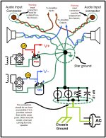
your post28 pic breaks the rule: close coupled signal wires.
a.) The RCA to amplifier signal wire PAIR must be close coupled all the way from the RCA to the amplifier.
b.) The Speaker pair must be close coupled all the way from the speaker terminals to the amplifier.
c.) The positive power supply pair must be close coupled all the way from the PSU to the amplifier.
d.) The negative power supply pair must be close coupled all the way from the PSU to the amplifier.
Wiring the "star ground" as you have shown brings BIG LOOPs into all those signal pairs.
Ok so I removed the PCB from the chassis and also removed the LED from under the board, but I still get that hum on the output... I don't really know what to look for after...
One thing though that I'm thinking and some of you might have missed. The amp has a protection circuit that as far as is just a delay for the amp. When I first assembled the amplifier the relay it wasn't "opening" so I guessed that something wrong was with the circuit but since it was just a delay I figured it would do no harm removing the relay and just shorting the connectors. Maybe I was wrong and the hum has something to do with that protection circuit?
When I removed the PCB from the chassis I tested each channel separately and not both at the same time.
Any ideas?
Attached are pictures of protection circuit on the board, and how I have shorted the relay. Never mind that. I tried attaching the photos but I got an error and I already contacted support about the error. So here is a google photos album instead with the photos! thank you!
https://goo.gl/photos/u3ZSTXqpYqsB3kZk8
If you remove R10 and R11 it will disconnect the power to the delay circuit.
Please post a photo of the underside of the board.
Please post a photo of the underside of the board.
Last edited:
If you remove R10 and R11 it will disconnect the power to the delay circuit.
Please post a photo of the underside of the board.
At this point I have removed the relay and shorted its connectors and the amplifier works. So no point in removing these resistors I guess. Here's a picture of the underside of the PCB.
https://goo.gl/photos/N4StmFWyTJV8YPQL8
Note that there was an error on the board on those two transistors at the delay circuit and I had to flip the two legs of the transistors. Our teacher said to do that.
Last edited:
Hi,
Using as is it in the drawing worked for me. All my amplifiers built are very quiet and free of noises. The most important when wiring the ground it is make sure they are connected to a one point and one point only and also twisted the voltages and audio wires.
I think Andrew you gave him an advice to read the DC voltage with the meter in AC was a good idea. I always recommend it when you do not have an scope. It will tell you immediately how good it is the dc filtering of the dc voltages. So I will remembered him to do the test and post the reading.
Hi,
morky : On thread 33 you mentioned you removed the relay and jumped the contacts so do not forget that to enable the relay you need to sense the speaker output to the relay detector. You need to find out how they sense the speaker output and remove it. Why just not remove all the components for the speaker protection circuit?
I think when Mark Whitney asked you to remove resistors R10 and R11 resistors was to isolate the speaker output from the speaker protection circuit.
Hi,
Using as is it in the drawing worked for me. All my amplifiers built are very quiet and free of noises. The most important when wiring the ground it is make sure they are connected to a one point and one point only and also twisted the voltages and audio wires.
I think Andrew you gave him an advice to read the DC voltage with the meter in AC was a good idea. I always recommend it when you do not have an scope. It will tell you immediately how good it is the dc filtering of the dc voltages. So I will remembered him to do the test and post the reading.
I tried measuring the Vac but my meter isn't that good and doesn't measure at the mVac range...
Hi,
morky : On thread 33 you mentioned you removed the relay and jumped the contacts so do not forget that to enable the relay you need to sense the speaker output to the relay detector. You need to find out how they sense the speaker output and remove it. Why just not remove all the components for the speaker protection circuit?
I think when Mark Whitney asked you to remove resistors R10 and R11 resistors was to isolate the speaker output from the speaker protection circuit.
I removed both resistors and the hum is still there... 🙁
Hi,
Okay, that will eliminated the noises coming from the speaker protection circuit. Then can you read the DC voltages with the meter in AC and post the reading. Read the voltages coming into the board and also at the speakers outputs. If you do not mind.
Okay, that will eliminated the noises coming from the speaker protection circuit. Then can you read the DC voltages with the meter in AC and post the reading. Read the voltages coming into the board and also at the speakers outputs. If you do not mind.
Using as is it in the drawing worked for me. All my amplifiers built are very quiet and free of noises. The most important when wiring the ground it is make sure they are connected to a one point and one point only and also twisted the voltages and audio wires.
Your amplifiers may be free of hum because you just happened to get lucky. As Andrew pointed out, the large loop areas you have in your drawing are a recipe for hum induction.
In addition, while your amp may be free of hum, you most certainly degraded the THD above a few hundred Hz with that star ground arrangement. In my LM3886 P2P vs PCB (with data) thread, I have shown the impact of various common DIY layouts. It's pretty obvious that the star ground is not the best option for THD. I explained why a few posts back in this thread.
Tom
Hi,
Well, that's means that I have been 3 times lucky. Like I said it is worked for me and I will recommended it as a reference to any one with hum problems. Any way this is not about my ground wiring. Now, lets try to concentrate and fix morky hum problem. Lets wait for the AC voltage reading.
Well, that's means that I have been 3 times lucky. Like I said it is worked for me and I will recommended it as a reference to any one with hum problems. Any way this is not about my ground wiring. Now, lets try to concentrate and fix morky hum problem. Lets wait for the AC voltage reading.
Now, lets try to concentrate and fix morky hum problem. Lets wait for the AC voltage reading.
You may have to wait a while. He said a few posts back that his voltmeter can't resolve voltages that low.
Tom
- Status
- Not open for further replies.
- Home
- Amplifiers
- Chip Amps
- LM3886 hum