Re: I should call it a day and run but........
No, Fred. you said it was "wrong", not "totally wrong".
My bad.
Fred Dieckmann said:did I mention that their inplementation of "soft start" is totally wrong, as Fred had mentioned?
No, Fred. you said it was "wrong", not "totally wrong".
My bad.
Well actually..............
"No, Fred. you said it was "wrong", not "totally wrong".
As an emitter follower to provide a low impedance for The ADJ terminal..... not as a slow start circuit. Sorry for any confusion I might have caused.
"No, Fred. you said it was "wrong", not "totally wrong".
As an emitter follower to provide a low impedance for The ADJ terminal..... not as a slow start circuit. Sorry for any confusion I might have caused.
I just wanted to point out that :
The circuit shown at the beggining of the thread not only does not improve regulation, but the 4.7uF capacitor causes reverse polarization of BE junctions of the auxiliary transistors and the adjustment pin of the regulators in case of output short circuit due to the lack of protection diodes
This may lead to transistor and regulator performance degradations and ultimately failures over time
Re: Well actually..............
nice try Fred. May I clarify for you that nobody was talking about adding a low-impedance to the ADJ pin? I thought you didn't bring "impedance" until a few posts later but what do I know, 🙂.
here is your original post:
"It is not a soft start circuit, which is more easily achieved by putting a cap across the resistor from the adjustment terminal to ground. The concept of the circuit is fine but the implementation is wrong. Since I believe this circuit is an adaptation of one of Mr. Sloan's maybe something was lost in the translation. I have not seen the original Sloan circuit. This is really a straight forward circuit when implemented correctly and not a bad idea in principle. Where did I drop the ball?
Which is the part you are disappointed in, not understanding exactly how the adjustment terminal works or how to correctly bias the emitter follower?
I was going to post a another circuit to do this but I honestly don't know if I could explain it well enough for everyone to use."
Hopefully we know better what you were talking about then. Again, thanks for your clarification and we still look forward to your correctly implemented soft start circuit as you had promised in the above post.
Fred Dieckmann said:"No, Fred. you said it was "wrong", not "totally wrong".
As an emitter follower to provide a low impedance for The ADJ terminal
nice try Fred. May I clarify for you that nobody was talking about adding a low-impedance to the ADJ pin? I thought you didn't bring "impedance" until a few posts later but what do I know, 🙂.
here is your original post:
"It is not a soft start circuit, which is more easily achieved by putting a cap across the resistor from the adjustment terminal to ground. The concept of the circuit is fine but the implementation is wrong. Since I believe this circuit is an adaptation of one of Mr. Sloan's maybe something was lost in the translation. I have not seen the original Sloan circuit. This is really a straight forward circuit when implemented correctly and not a bad idea in principle. Where did I drop the ball?
Which is the part you are disappointed in, not understanding exactly how the adjustment terminal works or how to correctly bias the emitter follower?
I was going to post a another circuit to do this but I honestly don't know if I could explain it well enough for everyone to use."
Hopefully we know better what you were talking about then. Again, thanks for your clarification and we still look forward to your correctly implemented soft start circuit as you had promised in the above post.
Re: Re: Re: Shall I proceed to PCB this circuit, then?
for C11,12
If steady current is 100mA, you allready need heatsinks.
Regards
tcpip said:Me quite confused. DO you mean to say that I've kept too little space ......
for C11,12
I kept the two regulators on the edges of the PCB, with their backs facing outwards, so that I could easily bolt heatsinks on them if needed.
If steady current is 100mA, you allready need heatsinks.
Regards
SY said:But on paper, there was an article by Errol Dietz of NSC in Electronic Design (Dec 14, 1989, p 92) showing the effects of load current on source inductance and noise in the 317. For example, at 10 ma (that's MILLIamps, not micro), the output inductance is about 5 uH. At 100 ma, it's dropped to about 1 uH. The noise curves show about a factor of three improvement between 10 ma and 55 ma.
Thanks.
Pardon my jumping in, but my arguably rather befuddled analysis tells me that if you place a cap between ADJ and ground, load regulation will suffer. The circuit - as drawn - achieves soft start without having the cap interfere once stable operating conditions are reached.
Now, whether tcpip wanted to know if the circuit did what Slone said it did or how to achive that with a transistor, I'm not sure.
Rune
Now, whether tcpip wanted to know if the circuit did what Slone said it did or how to achive that with a transistor, I'm not sure.
Rune
runebivrin said:Pardon my jumping in, but my arguably rather befuddled analysis tells me that if you place a cap between ADJ and ground, load regulation will suffer.
Rune
I think with a cap, load regulation will improve.
the resistor from the adj pin to the ground acts essentially like a voltage referrence (driven by the CCS from the adj pin). with a cap next to it, the ripple on the output voltage will get filtered throughthe cap, keeping the voltage on the adj pin thus the output pin constant.
Post#2Richard C said:Are you sure the schematic is correct? The transistors appear to provide 'soft start' rather than enhanced regulation.
Nearly 50 posts later and the verdict is......🙄
What is it that you want exactly?
"It is not a soft start circuit, which is more easily achieved by putting a cap across the resistor from the adjustment terminal to ground. The concept of the circuit is fine but the implementation is wrong. Since I believe this circuit is an adaptation of one of Mr. Sloan's maybe something was lost in the translation. I have not seen the original Sloan circuit. This is really a straight forward circuit when implemented correctly and not a bad idea in principle. Where did I drop the ball? "
Well, obviously it is a soft start circuit......... You are convinced of that now? I don't know what else to say to get the point across that I have been looking at this circuit from the standpoint a low impedance circuit for the ADJ to improve the performance of the regulator. This is what the original question was about, right? I should have the said circuit was intended for increasing the performance of the regulator and even asking if something might have miss copied from Mr. Sloans circuit. Adding one resistor from the base to ground would give a conventional bias scheme for an emitter follower. The other resistor value should be smaller since the current through these resistors should be much greater than the base current which is really an error term that will change the resistor ratios for the same voltage for different values of base current the particular device used.
I have really tried to be helpful and work towards answer the original posters question after explaining the desirable characteristic for the circuit and why the existing circuit does not meet these goals. I have a circuit designed that should work pretty well.
However.......... certain individuals seem bent on turning this into one of the Eddylike "You said.. I said... You meant.... I really meant "diatribes that I am thoroughly sick of. If someone wants to mail me about the circuit instead this pointless nonsense feel free.
just some thoughts:
...may be these "incompentent" designers at National and Thomson
are really using this circuit for soft start. And may be they are
not incompetent.
May be they simply found that a small signal transistor and
some SMD stuff need less space on the PCB than using a larger
capacitor in parallel to the lower resistor (fred's proposal for a
simple soft start).
It might be even cheaper than a large cap....
Please note the different source resistances for charging the cap
in the different topologies. The simple topologie would require
about 200 times more capacitance for the same time constant.
Re: Back to the origional question.........
Fred Dieckmann said:"same "incompetent" engineer"- quote from millwood
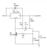
"I drew this schematic by putting together two schematics from Randy Slone's Audiophile Projects Sourcebook, the chapter on power supplies. He says that the transistors are used to enhance the regulation of the LM317/337. I am not familiar with how this works; don't remember seeing anything transistor-enhanced of this sort in any application notes. Can you give me any pointers or explanations?" -Quote from tcpip
You know ....... I spent a lot of time explaining why a low impedance at the ADJ terminal was desirable and reading the data sheets will show how putting a bypass cap across the ADJ terminal increases the PSRR.
janneman: irrelevant to the question
Also regulator noise is given as a percentage of output voltage. The larger the output voltage is, the larger the resistor from the ADJ to ground is for a given current from the ADJ terminal. Bypassing this resistor decreases noise as the impedance of the cap decreases with frequency. The output impedance also decreases as the capacitor impedance becomes lower than resistor from ADJ to ground. The lower the impedance at the ADJ the better the performance of the regulator.
janneman: irrelevant to the question
The intent of a follower circuit is to achieve this improvement. The soft start circuit under debate does not improve the regulation, PSRR, or noise of the regulator and putting the cap from the ADJ terminal to ground would be a much better use of the capacitor. Pay attention now..........
janneman: irrelevant to the question
A CORRECTLY DESIGNED EMITTER OR SOURCE FOLLOW AT THIS TERMINAL WOULD ENHANCE THE REGULATOR PERFORMANCE EVEN FUTHER JUST A CAPACITOR BYBASS OF THE ADJ TERMINAL.
Mr. Jung and White had this insight into improving LM317 performance 25 years ago with a zener in place of the resistor. If everybody ever stops running around in circles, maybe I will post a circuit. It would be futile at this point I'm afraid. We now return to our regularly scheduled sitcom.
janneman: at the peril of repeating myself: although in itself correct, irrelevant to the question. The question being: how does this improve etc. Answer: it doesn't.
janneman: please can someone educate me as to the difference between a slow-start and a slow-turn-on circuit, relevant to power supply regulators? Thank you.
Jan......... the only mysterious reading I did was reading tcpip asking
if this circuit could improve the regulator performance. I don't think he was looking for a slow start circuit but was looking for a circuit to improve the regulation.
janneman: Yoy contradict yourself. As you yourself said: "asking
if this circuit could improve the regulator performance" . That doesn't sound like "asking how thes could improve etc". You're blabbering, Fred. Show some character and move on.
I will admit most of the post here are off to a VERY SLOW START to providing him any help..... I think it is fine that people can find a slow start circuit in the data sheet, but that is not the circuit function tcpip is looking for.
janneman: How the hell do you know what he was looking for? He just wanted to understand the Sloane stuff.
Is it tcpip? 😕
runebivrin said:Pardon my jumping in, but my arguably rather befuddled analysis tells me that if you place a cap between ADJ and ground, load regulation will suffer. [snip]Rune
Exactly!
Jan Didden
millwood said:
I think with a cap, load regulation will improve.
the resistor from the adj pin to the ground acts essentially like a voltage referrence (driven by the CCS from the adj pin). with a cap next to it, the ripple on the output voltage will get filtered throughthe cap, keeping the voltage on the adj pin thus the output pin constant.
(I love this)
Millwood, you don't understand regulation. The ripple on the output needs to be fed back (remember feedback?) to the adjust pin to make sure that the ripple is counteracted by the regulator giving out more or less current to keep the output stable. With a cap on the ref, that feedback doesn't work, the reg works essentially as a follower, load regulation is all but absent. Basics, really.
Jan Didden
Re: What is it that you want exactly?
see, Fred, that's why we are confused. You first said admantly that it is NOT a soft start circuit. Now you said, equally admantly, that it IS a soft start circuit, albeit incorrectly implemented by the engineers at National, SGS, TI and a bunch others.
Can you please make up your mind? It cannot be both, right?
Are you?
you can look at this from whatever point you like, as long as you get to one, hopefully correct?, conclusion. It is when you come to two opposing conclusions that we don't know what you are talking about. Maybe you do, maybe you don't, either.
Is it?
"should", "would", "could". All wonderful words.
adding an addtion to my house will sure improve its resale value. But is that relevant to this discussion?
Yes. those "incompetent" engineerings from National and TI sure screwed up their datasheets.
to be helpful, one has to be at least consistent. Telling us that it is NOT a soft start circuit and then turning 180 degrees on that same issue isn't particularly help, don't you agree?
Not to mention telling us that the guys at National and TI all got it incorrectly implemented, for got knows how many years.
Not to mention that my breadboarded version does exactly what others have suggested: soft start.
not to mention that after this many posts, you haven't been able to produce one "correctly implemented" soft start circuit of your very own.
Not to mention that you still tried to argue you way out of a mistake of your ver own.
sure, the existing circuit doesn't make my coffee. But for a soft starter, it does what it said it does.
Well, then share it with us. Hopefully, it is more correctly implemented than the national / ti variety.
it is neccessary if you are dealing with slicky willie, 🙂
Fred Dieckmann said:"It is not a soft start circuit, which is more easily achieved by putting a cap across the resistor from the adjustment terminal to ground. The concept of the circuit is fine but the implementation is wrong. Since I believe this circuit is an adaptation of one of Mr. Sloan's maybe something was lost in the translation. I have not seen the original Sloan circuit. This is really a straight forward circuit when implemented correctly and not a bad idea in principle. Where did I drop the ball? "
Well, obviously it is a soft start circuit.
see, Fred, that's why we are confused. You first said admantly that it is NOT a soft start circuit. Now you said, equally admantly, that it IS a soft start circuit, albeit incorrectly implemented by the engineers at National, SGS, TI and a bunch others.
Can you please make up your mind? It cannot be both, right?
Fred Dieckmann said:........ You are convinced of that now?
Are you?
Fred Dieckmann said:I don't know what else to say to get the point across that I have been looking at this circuit from the standpoint a low impedance circuit for the ADJ to improve the performance of the regulator.
you can look at this from whatever point you like, as long as you get to one, hopefully correct?, conclusion. It is when you come to two opposing conclusions that we don't know what you are talking about. Maybe you do, maybe you don't, either.
Fred Dieckmann said:This is what the original question was about, right?
Is it?
Fred Dieckmann said:I should have the said circuit was intended for increasing the performance of the regulator and even asking if something might have miss copied from Mr. Sloans circuit.
"should", "would", "could". All wonderful words.
Fred Dieckmann said:Adding one resistor from the base to ground would give a conventional bias scheme for an emitter follower.
adding an addtion to my house will sure improve its resale value. But is that relevant to this discussion?
Fred Dieckmann said:The other resistor value should be smaller
Yes. those "incompetent" engineerings from National and TI sure screwed up their datasheets.
Fred Dieckmann said:I have really tried to be helpful
to be helpful, one has to be at least consistent. Telling us that it is NOT a soft start circuit and then turning 180 degrees on that same issue isn't particularly help, don't you agree?
Not to mention telling us that the guys at National and TI all got it incorrectly implemented, for got knows how many years.
Not to mention that my breadboarded version does exactly what others have suggested: soft start.
not to mention that after this many posts, you haven't been able to produce one "correctly implemented" soft start circuit of your very own.
Not to mention that you still tried to argue you way out of a mistake of your ver own.
Fred Dieckmann said:and work towards answer the original posters question after explaining the desirable characteristic for the circuit and why the existing circuit does not meet these goals.
sure, the existing circuit doesn't make my coffee. But for a soft starter, it does what it said it does.
Fred Dieckmann said:I have a circuit designed that should work pretty well.
Well, then share it with us. Hopefully, it is more correctly implemented than the national / ti variety.
Fred Dieckmann said:However.......... certain individuals seem bent on turning this into one of the Eddylike "You said.. I said... You meant.... I really meant "diatribes that I am thoroughly sick of.
it is neccessary if you are dealing with slicky willie, 🙂
Fred Dieckmann said:If someone wants to mail me about the circuit instead this pointless nonsense feel free.
ChocoHolic said:just some thoughts:
...may be these "incompentent" designers at National and Thomson
are really using this circuit for soft start.
they are using it for "slow turn-on", 🙂, an incorrectly implemented "slow-turn on" that is, 🙂. If you believe in Fred and his indepth knowledge about the device.
maybe those "incompetent" designers at national and Thomson do know what they are talking about and it is some of us who are clueless.
Given what has happened on this board, i wouldn't say that's not possible.
Since we are back to productive post....
"just some thoughts:"
Excellent observations. There real limits to increasing resistor vaules at
the adjustment terminal due to actual current from the adjustment terminal which is an error term for the current from the programming current the resistor from Vout to ADJ terminals. Too large of a cap is also a problem due to the large discharge currents during fault conditions at the input or output of the regulator. A fet would give even more flexibility for a large resistor and a small cap.
"and it is some of us who are clueless"
Remember, you said that and not me.............
Attachments
janneman said:
(I love this)
Millwood, you don't understand regulation. The ripple on the output needs to be fed back (remember feedback?) to the adjust pin to make sure that the ripple is counteracted by the regulator giving out more or less current to keep the output stable. With a cap on the ref, that feedback doesn't work, the reg works essentially as a follower, load regulation is all but absent. Basics, really.
Jan Didden
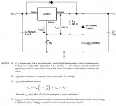
Jan, I am pretty sure that I don't understand regulation. more than that, I am also sure that the guys at National don't have a clue about regulation either. This is what they said about that capacitor. Pay attention to Note C.
This is straight from National's datasheet, Page 4.
since it can be hard to read, please allow me to type it up here: "Cadj is used to improve ripple rejection; it prevents amplification of the ripple as the output voltage is adjusted higher." Isn't datasheet wonderful?
Hope it helps.
Attachments
Re: Since we are back to productive post....
Fred, we had been on the productive posts, until someone told us that this is not a soft start circuit.
Hm, do you remember who that person was?
🙂
Fred Dieckmann said:"just some thoughts:"
Fred, we had been on the productive posts, until someone told us that this is not a soft start circuit.
Hm, do you remember who that person was?
🙂
- Status
- Not open for further replies.
- Home
- Amplifiers
- Solid State
- LM317-based regulated PSU: how does this thing work?