Steady current is too high (why wasting ca 6Watts)?
Reduces noise and increases regulation. See the data sheets and app notes.
Not as dissapointed as I am.
"After reading the second part, it seems that Jan and I were just right in our posts and nothing more has been added. Actually I'm a little disappointed, but maybe I was just expecting too much."
"After reading the second part, it seems that Jan and I were just right in our posts and nothing more has been added. Actually I'm a little disappointed, but maybe I was just expecting too much."
I am disappointed that some of us explained how the circuitry works before reading the datasheet, 🙂
Got a bad headache and ain't thinking too clearly, but howz bout tying the input of a follower to the resistive divider junction, and connecting the ADJ pin of the 3-term reg chip to the follower's emitter/source? IOW, the ADJ would no longer be connected directly to the junction of the resistive divider. The ADJ pin would be looking into a nice low-impedance node (at least lower than what any resistive divider could provide).
jonathan carr
jonathan carr
Sorry interupted by breakfast and edit time limit.
"After reading the second part, it seems that Jan and I were just right in our posts and nothing more has been added. Actually I'm a little disappointed, but maybe I was just expecting too much."
It is not a soft start circuit, which is more easily achieved by putting a cap across the resistor from the adjustment terminal to ground. The concept of the circuit is fine but the implementation is wrong. Since I believe this circuit is an adaptation of one of Mr. Sloan's maybe something was lost in the translation. I have not seen the original Sloan circuit. This is really a straight forward circuit when implemented correctly and not a bad idea in principle. Where did I drop the ball?
Which is the part you are disappointed in, not understanding exactly how the adjustment terminal works or how to correctly bias the emitter follower?😕
I was going to post a another circuit to do this but I honestly don't know if I could explain it well enough for everyone to use.
Re: Sorry interupted by breakfast and edit time limit.
didn't I mention I was disappointed that people say things before reading the datasheet?
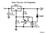
Let's just say that on page 14 of a certain datasheet the design team at National called such a circuit "Slow turn-on 15v regulator".
I understand that some of us know far more about lm317 than those engineers at National but that's not without exception.
edit: here is a snapshot of that National circuitry. enjoy.
Fred Dieckmann said:[BIt is not a soft start circuit, which is more easily achieved by putting a cap across the resistor from the adjustment terminal to ground. The concept of the circuit is fine but the implementation is wrong. [/B]
didn't I mention I was disappointed that people say things before reading the datasheet?
Let's just say that on page 14 of a certain datasheet the design team at National called such a circuit "Slow turn-on 15v regulator".
I understand that some of us know far more about lm317 than those engineers at National but that's not without exception.
edit: here is a snapshot of that National circuitry. enjoy.
Attachments
Pedja said:What a thread!!!
Too much so; I've got an actual regulator that needs troubleshooting, and this has been so entertaining that I'm not getting my work done.
SY said:Reduces noise and increases regulation. See the data sheets and app notes.
Hi,
I can't find this data (about optimal 100mA steady current from LM317/337).
Any link?
Regards
moamps said:
Hi,
I can't find this data (about optimal 100mA steady current from LM317/337).
Any link?
Regards
on page 8. It is 100ua.
Understanding the data sheet and reading the data sheet
The open loop output impedance is a fuction of the DC current. Go look at a data sheet for a power transistor and note the Ic verses Vbe
curve. The change in Vbe divided by the change emitter current. There is a good clue in the regulator data sheet in that they specifiy the output impedance with 0.5 amp DC load. I bet very few three terminal regulator applications need this kind of current but showing the output impedance at this load results in lower numbers. Many times standard measurement conditions are used for certain device types so that you are comparing the performance between different vendors parts under the same conditions so that one part does not look superior due different operating conditions. Data sheets are written to present parts in their best light. Don't forget that one the main functions of a data sheet is as an advertising document for the part. Preloading for audio regulators is a very old practice. It is the same principle as the reason for Class A outputs in power amplifiers.
Re: Sorry interupted by breakfast and edit time limit.
Fred,
I think you meant my remark about disappointment, not Millwood's.
I know how the adjustment terminal works and also how to calculate the resistors. I'm familiar with these regulators. That's not the point at all. No, what I meant was that after the explanation of soft starting by Jan and me, you started a two-piece post urging everyone to read the datasheet in between. At that moment I expected that you were going to come up with something completely different. But that appeared not to be the case. Because of your reputation of in-depth knowledge I had expected more, that was the only reason of my disappointment. So, just a misunderstanding. I hope it is cleared now.
I don't think something was lost in the translation of Mr. Slone's book; the circuit is just a familiar one from the databook of the manufacturer. Mr. Slone seems to have just copied it and added the wrong explanation.
Although a soft start circuit with just a capacitor across the grounded adjustment resistor would be easier, as you propose, the capacitor value should be a lot bigger than in the circuit shown. The adjustment resistors have a pretty low values because of the current tolerance of the adjustment terminal.
As for the remark of Jonathan: his proposal will work, but with a slight decrease of temperature stability, just as you (Fred) already mentioned. But that is dependent on output voltage; at lower voltages it will be more prominent.
Steven
Fred Dieckmann said:"After reading the second part, it seems that Jan and I were just right in our posts and nothing more has been added. Actually I'm a little disappointed, but maybe I was just expecting too much."
It is not a soft start circuit, which is more easily achieved by putting a cap across the resistor from the adjustment terminal to ground. The concept of the circuit is fine but the implementation is wrong. Since I believe this circuit is an adaptation of one of Mr. Sloan's maybe something was lost in the translation. I have not seen the original Sloan circuit. This is really a straight forward circuit when implemented correctly and not a bad idea in principle. Where did I drop the ball?
Which is the part you are disappointed in, not understanding exactly how the adjustment terminal works or how to correctly bias the emitter follower?😕
I was going to post a another circuit to do this but I honestly don't know if I could explain it well enough for everyone to use.
Fred,
I think you meant my remark about disappointment, not Millwood's.
I know how the adjustment terminal works and also how to calculate the resistors. I'm familiar with these regulators. That's not the point at all. No, what I meant was that after the explanation of soft starting by Jan and me, you started a two-piece post urging everyone to read the datasheet in between. At that moment I expected that you were going to come up with something completely different. But that appeared not to be the case. Because of your reputation of in-depth knowledge
I had expected more, that was the only reason of my disappointment. So, just a misunderstanding. I hope it is cleared now.I don't think something was lost in the translation of Mr. Slone's book; the circuit is just a familiar one from the databook of the manufacturer. Mr. Slone seems to have just copied it and added the wrong explanation.
Although a soft start circuit with just a capacitor across the grounded adjustment resistor would be easier, as you propose, the capacitor value should be a lot bigger than in the circuit shown. The adjustment resistors have a pretty low values because of the current tolerance of the adjustment terminal.
As for the remark of Jonathan: his proposal will work, but with a slight decrease of temperature stability, just as you (Fred) already mentioned. But that is dependent on output voltage; at lower voltages it will be more prominent.
Steven
moamps said:
Hi,
I can't find this data (about optimal 100mA steady current from LM317/337).
Any link?
Well, I've got a slow dial-up connection so I can't really get you a link. But on paper, there was an article by Errol Dietz of NSC in Electronic Design (Dec 14, 1989, p 92) showing the effects of load current on source inductance and noise in the 317. For example, at 10 ma (that's MILLIamps, not micro), the output inductance is about 5 uH. At 100 ma, it's dropped to about 1 uH. The noise curves show about a factor of three improvement between 10 ma and 55 ma. NSC may have this paper on their website- it was also reprinted in Pease, "Troubleshooting Analog Circuits" as an appendix.
Re: Re: Shall I proceed to PCB this circuit, then?
Anything else? And thanks for all the inputs so far. I'm learning faster than any book could have taught me. 🙂
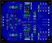
Yes, boss. (Never argue with a moderator. -- old jungle saying.) Hope the image below will indicate what I've done. Am now wondering whether it would have been better to just make space for one of those white box-shaped 5W resistors instead of three cylindrical ones?SY said:Double that power rating. A little margin is a good thing.
Me quite confused. DO you mean to say that I've kept too little space or too much space for the 'lytics? I have some 2200uF 65V caps at home, and they are 2cm in dia, the same as the space I've kept on the PCB. I was hoping that 4700uF 30V would be about the same size.moamps said:C11 and 12 have bigger dimensions (can be electrolytic).
This has already been discussed threadbare by minds more able than mine. I've attached a modified PCB below showing the added resistors. PCB layout seems to be about the only contribution that I can make to a discussion as sophisticated as this one. 😀Steady current is too high (why wasting ca 6Watts)?
I kept the two regulators on the edges of the PCB, with their backs facing outwards, so that I could easily bolt heatsinks on them if needed. I have some neat finned AL extrusion heatsinks (unlike the bent-sheet types which most small heatsinks seem to be) which are about as wide as a TO-220 package. I guess those will easily fit on the regulators without disturbing anything else on the PCB.What about heatsinks on regulators?
Anything else? And thanks for all the inputs so far. I'm learning faster than any book could have taught me. 🙂
Attachments
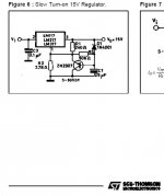
millwood said:to make matters worse, the same "incompetent" engineer works at SGS Thomson and TI, to name a few. Here is the SGS' version of the slow turn-on circuitry.
Fred and Millwood, are you guys serious? I mean not trying some private joke or anything?
Fred says " the intent is ..." Are you now in mindreading, Fred? This is a slow start, delayed start or whatever. That Slone doesn't get it, doesn't make it a different circuit. And Millwood, what do you mean by "incompetent engineers?". This is a slow start circuit that works. There are probably an infinity of other slow start circuits that also work. So?
Get a life, guys!
Jan Didden
PS Steven, your patience is exemplary. You're a better man than I.
Back to the origional question.........
"same "incompetent" engineer"- quote from millwood
"I drew this schematic by putting together two schematics from Randy Slone's Audiophile Projects Sourcebook, the chapter on power supplies. He says that the transistors are used to enhance the regulation of the LM317/337. I am not familiar with how this works; don't remember seeing anything transistor-enhanced of this sort in any application notes. Can you give me any pointers or explanations?" -Quote from tcpip
You know ....... I spent a lot of time explaining why a low impedance at the ADJ terminal was desirable and reading the data sheets will show how putting a bypass cap across the ADJ terminal increases the PSRR. Also regulator noise is given as a percentage of output voltage. The larger the output voltage is, the larger the resistor from the ADJ to ground is for a given current from the ADJ terminal. Bypassing this resistor decreases noise as the impedance of the cap decreases with frequency. The output impedance also decreases as the capacitor impedance becomes lower than resistor from ADJ to ground. The lower the impedance at the ADJ the better the performance of the regulator. The intent of a follower circuit is to achieve this improvement. The soft start circuit under debate does not improve the regulation, PSRR, or noise of the regulator and putting the cap from the ADJ terminal to ground would be a much better use of the capacitor. Pay attention now..........
A CORRECTLY DESIGNED EMITTER OR SOURCE FOLLOW AT THIS TERMINAL WOULD ENHANCE THE REGULATOR PERFORMANCE EVEN FUTHER JUST A CAPACITOR BYBASS OF THE ADJ TERMINAL.
Mr. Jung and White had this insight into improving LM317 performance 25 years ago with a zener in place of the resistor. If everybody ever stops running around in circles, maybe I will post a circuit. It would be futile at this point I'm afraid. We now return to our regularly scheduled sitcom.
Jan......... the only mysterious reading I did was reading tcpip asking
if this circuit could improve the regulator performance. I don't think he was looking for a slow start circuit but was looking for a circuit to improve the regulation. I will admit most of the post here are off to a VERY SLOW START to providing him any help..... I think it is fine that people can find a slow start circuit in the data sheet, but that is not the circuit function tcpip is looking for. Is it tcpip? 😕
janneman said:This is a slow start circuit that works.
sorry, Jan, this is certainly NOT a slow start circuit. As those "incompetent" engineers at National put it, this is simply a slow turn-on circuit. While "the concept of the circuit is fine, but the implementation is wrong", as Fred had correctly pointed out in one of his earlier posts (here: http://www.diyaudio.com/forums/showthread.php?postid=331667#post331667)
I would suggest that we all hold our breadth until Fred releases his correctly implemented "slow start" circuit.
In the meantime, everyone, especially those "incompetent" engineers at National, please try to understand "how the adjustment terminal works or how to correctly bias the emitter follower". OK?
janneman said:And Millwood, what do you mean by "incompetent engineers?".
They are incompetent because of the incorrect implementation, as Fred had pointed out; because of their inability to understand how their own design works; because of their demonstrated incompetency in biasing an emitter follower correctly; because of ... did I mention that their inplementation of "soft start" is totally wrong, as Fred had mentioned?
🙂
PS: Jan, it was a good-natured joke. Don't take it too seriously. It is Sunday anyway, 🙂.
Re: Back to the origional question.........
Thank you Fred for bringing in all "regulation, PSRR, or noise" into this discussion: we laypersons certainly didn't think about it in prior discussions and I am sure they all are relevant and key to understand how the "soft start" circuitry works.
But I have to take exception with your calling it a soft start circuit. as you had correctly pointed out a few posts ago, the concept here is fine but the implementation is all wrong. Those guys at National, SGS Thomson, TI and potentially other places totally botched the job and this stuff in their datasheet is clearly wrong.
I breadboarded this thing a while ago. while the voltage does raise slowly on the output pin, I suspect it is because of my two DMMs not working properly.
We eagerly await your circuitry that will show us, and those guys at national, how to correctly implement a soft start on their devices while improving "regulation, PSRR, or noise".
Fred Dieckmann said:[BThe soft start circuit does not improve the regulation, PSRR, or noise of the regulator[/B]
Thank you Fred for bringing in all "regulation, PSRR, or noise" into this discussion: we laypersons certainly didn't think about it in prior discussions and I am sure they all are relevant and key to understand how the "soft start" circuitry works.
But I have to take exception with your calling it a soft start circuit. as you had correctly pointed out a few posts ago, the concept here is fine but the implementation is all wrong. Those guys at National, SGS Thomson, TI and potentially other places totally botched the job and this stuff in their datasheet is clearly wrong.
I breadboarded this thing a while ago. while the voltage does raise slowly on the output pin, I suspect it is because of my two DMMs not working properly.
We eagerly await your circuitry that will show us, and those guys at national, how to correctly implement a soft start on their devices while improving "regulation, PSRR, or noise".
I should call it a loss and run for it but........
"did I mention that their inplementation of "soft start" is totally wrong, as Fred had mentioned?"
I never intend to say that the circuit is a failure as a slow turn on circuit. Until the cap charges up enough for the base emitter junction to be unbiased the ADJ terminal follows the emitter and the base follows the charging capacitor. Looks like a slow start circuit to me.......
"did I mention that their inplementation of "soft start" is totally wrong, as Fred had mentioned?"
I never intend to say that the circuit is a failure as a slow turn on circuit.
Until the cap charges up enough for the base emitter junction to be unbiased the ADJ terminal follows the emitter and the base follows the charging capacitor. Looks like a slow start circuit to me.......- Status
- Not open for further replies.
- Home
- Amplifiers
- Solid State
- LM317-based regulated PSU: how does this thing work?