A minor errata in the schematic shown in post #18 above - R6 and R9 (current-limiting resistances for the Zener shunt regulator) have to be larger than the 47 ohms shown, or the dissipation will be unreasonably high. A value in the range of 220..470 ohms seems to work fine, and has negligible impact on the previous simulation results (The error occurred because I was initially working with lower +/- 18V rails, for which 47 ohms is reasonable).
It might also help to get rid of the Zener shunt regulator altogether and replace it with a 78L15/79L15 regulator pair, at a minor cost in the form of a higher BoM.
It might also help to get rid of the Zener shunt regulator altogether and replace it with a 78L15/79L15 regulator pair, at a minor cost in the form of a higher BoM.
Dear Linuxguru,
Thats a really interesting idea to make a clone with nested feedback... I cannot wait your listening tests! So you think its possible to have lesser THD levels with inverted design for both stages?
And a request;
As I understand you have a really working LM1875 model! Thats what I strongly need at these days.. In fact I have one LM1875 and one LM3886 models dowloaded from somewhere but none of them works!
So may you share your LM1875 model if possible?
> interesting idea to make a clone with nested feedback...
Not my original idea, really - it dates back a long time, to Walt Jung's composite op-amp/buffer, and maybe even earlier. Mauro Penasa has a very popular and excellent design based on the LM318 and LM3886 on this forum - search for MyRef RevC or similar.
> So you think its possible to have lesser THD levels with inverted design for both stages?
It depends on the common-mode distortion performance of the op-amp/chipamp in question - voltage-shunt inverting configurations are generally better when the common-mode distortion is not too good, because both the inputs are stuck at ground potential without voltage swing.
> So may you share your LM1875 model if possible?
Sure - it was posted by Pedja a while ago in some other forum. It seems to work for me, and has passed basic sanity checks. What I'd really like is a working LM3875 model.
Attachments
Thanks Linuxguru...
I was following Mauro's MyRef project however I couldnt have a chance to make one.. He was using the LM3886 as V/I converter, but yours looks some different.. Am I right?
I was following Mauro's MyRef project however I couldnt have a chance to make one.. He was using the LM3886 as V/I converter, but yours looks some different.. Am I right?
Hi - this looks like an interesting project - pretty impressive spec with combination of low-cost components..
I have a couple of questions:
- I guess this aproach could be applied to likes of TDA2030/2040/2050 as well? Am I wrong?
- Regarding to above: is there a "construction method" that can be applied without computer simulations? I mean - can some hobbist tweak circuits like above to accomodate TDA chips as well (without blowing components) or is such design more involved?
- Another (rather unrelated) question: could be such approach useful for headphone amp - with LM4562 into LM6182?
>I guess this aproach could be applied to likes of TDA2030/2040/2050 as well?
Yes, the general principle of a nested gainclone will work, with improved distortion specs, with a TDA-series chipamp also. However, there are no published SPICE models of those chipamps, which makes the stability analysis a bit tricky.
>is there a "construction method" that can be applied without computer simulations? I mean - can some hobbist tweak circuits like above to accomodate TDA chips as well (without blowing components) or is such design more involved?
Without the SPICE model, the analysis becomes tricky. The main issue is stability (from oscillation), i.e. adequate phase margin. It is possible to do this by trial-and-error, even with the TDA chipamps, as follows:
1) Start with the minimum stable closed-loop gain for the inner nested amp (TDA chipamp).
2) Build and check that the overall configuration is stable.
3) Gradually increase the inner gain for best audible sonics (by listening).
4) If the combination becomes unstable, back off and reduce the closed-loop gain for the chipamp.
Your best bet is the TDA2050, with its Class-AB output stage, for the power stage. It will likely remain stable with exactly the same values that I have shown for the LM1875, but with slightly higher distortion numbers.
> could be such approach useful for headphone amp - with LM4562 into LM6182?
It will work even for lower powered buffers, but I am not familiar with the LM6182. The LM4562 is quite extraordinary in its overall specs, but is comparatively expensive, and has a 3rd-harmonic character to its distortion at moderate swings. The combination needs to be simulated to determine the overall sonic character. You may find that some other opamps like the OPA37 or LT1469 may give better results as the outer op-amp for a head-amp/buffer.
Many thanks for the informative reply!
I'm sorry but this reply made me to come up with some more questions (admittedly slightly unrelated to the OP):
- Now, if TDA chips have worse distortion spec - would having a "super-nice" opamp yield any tangible advantage over "simpler" opamps like OPA2132 - or even TL072?
- Would it be possible to adapt such circuit to "non-opamp" TDA amp-chips - like TDA2009 etc? Or is there some other trick to "improve" these?
- Lastly, would it be possible to do something similar with a LM386 and some cheaper opamp?
Hi,
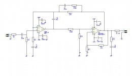
I am very interested in the concept of taking a cheap TDA2030 and improving it with a nested feedback loop. To this end I have draw up a version of your design based on a TDA2030.
Could you confirm that I have it right. I tried to make it easier to read so I could understand it better. So the drawing looks different to yours. I have just stuck your values in for now, clearly they will need reworking. I have put the amp and opamp on the same rails 15V as this is sufficient for the TDA2030 and the NE5532 can cope with 15V.
I wondered if it would be sensible to have an option for a resistor in parralel with C6 so the gain of the NE5532 loop could be reduced if required for stability. At the moment the design will vary with the open loop gain of the NE5532, but a 1M or poss smaller resistor would define the gain. What do you think?
Drawing below (hopefully) Regards, Andrew
Attachments
The NE5532's gain is the overall gain of 28, set by R11 and R8 minus the TDA2030's gain of 23, set by R2 and R6, so five. If you want to reduce that, you only need to reduce the value of R11.
Why would you want the 0R22 Ohm resistor at the output?
Why would you want the 0R22 Ohm resistor at the output?
The overall closed-loop gain of both op-amps is 28, and the closed-loop gain of the TDA is 23. That forces the swing at the output of the NE5532 to be fairly low - less than 1V peak. However, the closed-loop gain of the combination is not 5, it's still 28.
You can use a high-value resistance in parallel with the 68pF Integrator/dominant pole capacitance to reduce the dependence on the open-loop gain of the NE5532. I need to plug the values into LTSpice to see what's reasonable, but 1M looks ok.
Some errata in the TDA2050 schematic:
The outer feedback should be taken outside of the 0.22 ohm resistor at the output of the chipamp. This is important for stability, as well as controlling H3.
The Boucherot cell should be 10R (or lower) + 100n. This isn't actually necessary for the LM1875, but is probably helpful for stability - it contributes a few degrees of phase margin.
The input network should be have a 27k or similar to ground.
To anti:
1) You can use a lower distortion op-amp than the NE5532, but it will not necessarily improve the sonics of the combination. Stability may be harder to obtain with a very high-gain, fast, low-distortion outer op-amp. It may be worth checking out the opa37, lt1208 and lt1469. lm4562 is probably overkill, and may not stabilize easily in this application.
2) Fixed-gain chipamps like the TDA2009 may also work, but again, without a Spice model it may be tricky to stabilize the nested combo.
3) LM386 with a cheap op-amp - should work. Where I live, it's harder to obtain an LM386 than a TDA2050 or an LM1875.
You're right. The NE5532's contributions is not 28-23=5, it is 28/23=~1,2.linuxguru said:The overall closed-loop gain of both op-amps is 28, and the closed-loop gain of the TDA is 23. That forces the swing at the output of the NE5532 to be fairly low - less than 1V peak. However, the closed-loop gain of the combination is not 5, it's still 28.
Hi - thanks again for the informative answer.
For the "TDA" combos, I meant actually if the likes of TL07x would be "okay" (not trying to "repair" their spec with a "super" opamp). I guess bad wording.
I have a couple of lm386 I'd like to use (and a TDA2009 in an old amp I'd like to revamp). This approach seems like a good solution.
What I also considered - for the lm386 - would it be possible to simplify the "nested opamp" approach and use a single FET or a BJT nested/wrapped around the chip-amp (instead of the opamp - similar to some composite RIAA pres but without the frequency correction curve), taking the neg. feedback signal from the output? Has this been done yet? Any pointers perhaps?
Hi linuxguru
Thanks for your feedback.
The 27K was a typo, I have also added the HF filter which I had left off.
Thanks for the info on the 0.22R, I thought it was just to isolate the output from cable capacitance. Do you know the mechanism by which it reduces H3 or was that discovered impirically.
Your right 1M probably isn't required with an amp like the NE5532 and with the TDAs gain being defined. However I worked on a compound opamp design in which the origonal designer had not controled the open loop gains of either of the opamps, relying entirely on the single loop to control the behaviour and they went unstable all the time as the loop characteristics changed. So I am a bit over sensitised to leaving opamps open loop locally, even if the entire loop gain is controlled. I have added a location for the 1M resistor, I don't have to fit it if its not required or detrimental.
However I have found in the past that controling the open loop gain of internal parts of an amplifer so that it is flat accross the audio bandwidth can improve the sound quality. So it may be worth me doing some experiments to see what effect it does have.
Thanks for your help,
Regards,
Andrew
I plugged a gain-limiting resistance in parallel with C4 into LTSpice, and there is minimal impact on distortion and sonics between 470k to 1M, and up to 10 dB higher distortion at 100k. On the whole, the impact is minimal, so one might as well include a 330k..470k gain-limiting resistor for repeatable stability, especially with faster or higher-gain opamps like the LM4562 or LT1469. I'll post an updated schematic with the resistor and a slightly optimized compensation network in due course.
Using an LT1208 with a slightly tweaked gain and compensation network actually shows greater phase margin (up to 80-85 degrees) compared to ~70 degrees with the NE5532. I don't think it matters much to the sonics, but it might be worthing rolling op-amps and auditioning.
Using an LT1208 with a slightly tweaked gain and compensation network actually shows greater phase margin (up to 80-85 degrees) compared to ~70 degrees with the NE5532. I don't think it matters much to the sonics, but it might be worthing rolling op-amps and auditioning.
Hi Linuxguru!
Some more questions:
- would it be much different if a NE5534 was used instead of a NE5532 (f.e. in a "monobloc" board?)
- would it be possible then to take the signal from NE5534's "5-pin" - the compensation pin, bypassing the output stage (since the feedforward was omitted)?
- if a NE5532 was used, would it be possible to use the second opamp as a servo and WHERE should it be placed for stability and precision?
- Would it be much different if NE5532 was A-class biased (f.e. 6k8 to "+" supply)?
Just a question: this way, we are getting closer and closer to the Jung's circuit, no? But the 0.22R resistor is used as another "error" sensor (Jung has different config)? (link)
> would it be much different if a NE5534 was used instead of a NE5532 (f.e. in a "monobloc" board?)
Should work, since there is external compensation C4.
> would it be possible then to take the signal from NE5534's "5-pin" - the compensation pin, bypassing the output stage (since the feedforward was omitted)?
Depends on the drive capability from the VAS (?) of the NE5534, but perhaps possible if the resistor network at the input(s) of the chipamp is made higher impedance, say of the order of ~10k.
> if a NE5532 was used, would it be possible to use the second opamp as a servo and WHERE should it be placed for stability and precision?
I haven't thought about a DC servo yet.
> Would it be much different if NE5532 was A-class biased (f.e. 6k8 to "+" supply)?
Not much - at low swings (< 1V), the NE5532 seems to have fairly low distortion already. I'll plug in the 6.8k resistor later and check - it's an inexpensive improvement.
> Is it possible to compensate the range of National Chipamps when used at a gain = 2?
In the sims, the LM1875 can be used below the recommended gain of 10 with suitable compensation. However, I'm not sure that it extends all the way to a gain of 2. For unity gain or similar operation, the TI/Burr-Brown OPA549 family may be more useful, since they're unity-gain stable.
Hi,
the NE5532/4 is not optimum for a DC servo.
The LF411 is excellent for DC servo duty.
There are a number of more modern FET input opamps that can do even better, but is better needed?
the NE5532/4 is not optimum for a DC servo.
The LF411 is excellent for DC servo duty.
There are a number of more modern FET input opamps that can do even better, but is better needed?
I have been using a similar circuit for several years now, but with the
differences of the op amp runs on +- 15 volts, output +- 36 volts
I am wondering if this cct will still work as well if the op amp voltage is reduced and the input divider network to the LM1875 reduced by half.
This is optimal for me because the output is not limited to the op amp's
maximum supply voltage.
- Status
- Not open for further replies.
- Home
- Amplifiers
- Chip Amps
- LM1875 nested Gainclone