the direct distance from +ve power pin to -ve power pin is ~5mm.
The length of track and components around the decoupling loop is ~200mm.
If the HF decoupling is to work as intended by the manufacturer that long route must be reduced. Getting it down to 50mm would be a start, 20mm would be better.
The length of track and components around the decoupling loop is ~200mm.
If the HF decoupling is to work as intended by the manufacturer that long route must be reduced. Getting it down to 50mm would be a start, 20mm would be better.
i feel there should be a single Gnd connector on the ground track, may be in the center or if 2 connectors are required, they should be close
i feel there should be a single Gnd connector on the ground track, may be in the center or if 2 connectors are required, they should be close
Hi have a look on this PCB Layout.
Attachments
Hi have a look on this PCB Layout.
Lolzzz, may be u want to say that here i have done the same thing, This one was made by me only.. But there i am creating the ground plane on my amplifier side.. so there is no ground looping. Even ur PCB is also fine if u use the power supplied suggested by me in this layout. The power supply is not having ground plane in this case
Lolzzz, may be u want to say that here i have done the same thing, This one was made by me only.. But there i am creating the ground plane on my amplifier side.. so there is no ground looping. Even ur PCB is also fine if u use the power supplied suggested by me in this layout. The power supply is not having ground plane in this case
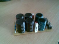
You are right Pa Jee.have a look on my supply pcb & revert if some improvements required.
Or is it good to opt for HARD Wired amp. plz suggest
http://www.diyaudio.com/forums/chip-amps/170095-hi-cap-ps-carlos-fm.html
Last edited:
Ground plane does not avoid ground loops. It's better to ensure that each ground returns on its own way on the common point.
My opinion has been and remains:
One must understand how and why a ground plane works and one must use this knowledge to design the ground plane to suit the application.
If one cannot meet any of those criteria, then do not attempt a ground plane.
One must understand how and why a ground plane works and one must use this knowledge to design the ground plane to suit the application.
If one cannot meet any of those criteria, then do not attempt a ground plane.
Hi AndrewT,
yes you are right. I have no idea about ground plane.
will you please elaborate?
Ok tell me one thing is the layout of component is ok?if there any relocation is required please suggest so that i can re-do the PCB layout.
yes you are right. I have no idea about ground plane.
will you please elaborate?
Ok tell me one thing is the layout of component is ok?if there any relocation is required please suggest so that i can re-do the PCB layout.
I do not fully understand the how nor the why and I certainly can't design a ground plane to suit the application.
I cannot offer any assistance.
I know my limitations. I take pride in being able to recognise those limitations.
I cannot offer any assistance.
I know my limitations. I take pride in being able to recognise those limitations.
I do not fully understand the how nor the why and I certainly can't design a ground plane to suit the application.
I cannot offer any assistance.
I know my limitations. I take pride in being able to recognise those limitations.
Hi AndrewT,
I have seen various similar implementations on the net.
I agree with you that doing a job whose result is not fruitful is not required.
So now i am going to hard wire the complete job. i.e. Power supply & amp.
in fact one channel power supply is completed.
thanks for your help & support.🙂
do you remember this post?the direct distance from +ve power pin to -ve power pin is ~5mm.
The length of track and components around the decoupling loop is ~200mm.
If the HF decoupling is to work as intended by the manufacturer that long route must be reduced. Getting it down to 50mm would be a start, 20mm would be better.
I cannot offer any better than that.
I'm working on a 3886 PCB design at the moment. You can place the smaller decoupling power capacitors left of the chip where the power pins (1,4,5) are located without difficulty - within 20mm. Don't be afraid to use narrower tracks or lose symmetry to get all the components as close to the chip as physically (and safely) possible. Your design is much neater than mine (damn it!) 🙂
Something easy to fix:
Cz (the zobel capacitor) should be connected to power ground, not signal ground.
So on the PCB it just needs to be moved slightly so that it goes to the left or down, instead of to the right.
Cz (the zobel capacitor) should be connected to power ground, not signal ground.
So on the PCB it just needs to be moved slightly so that it goes to the left or down, instead of to the right.
Something easy to fix:
Cz (the zobel capacitor) should be connected to power ground, not signal ground.
So on the PCB it just needs to be moved slightly so that it goes to the left or down, instead of to the right.
Hi ,
Kuldeep Singh PA Jee : Thanks.
AndrewT : Yes i remember that post. You are A good teacher for students like Me. Perhaps i um unable to understand the seriousness what u are talking about n will be glad fi you please explain. As told Low res photograph of
3.3mfd/100volt will be mounted directly on chip pins.my supply PCB
Random: Thanks for such appreciating words. i am working on your suggestion.
Godfrey: Thanks for the Hint.Actually Cz is connected to Power ground but the trace connecting star groud power & Power G was missed.
Now i have corrected the layout.
Attachments
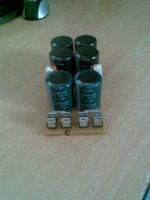
looks Cute... 🙂 Good work... neeraj...
I am too going to start a PCB for the same chip AMP. Can you tell me what pcb tool did u use?
And thanks to other members here for giving valuable tips. Sure this would get me success too.
http://www.national.com/an/AN/AN-1192.pdf
referring above application note I wish to go for BR100 configuration.
I have plans to use two smps rating 4 amp 20V DC for dual supply. This would reduce the size of filter capacitor. Also this supply is readily available in market at cheap ,as used for Laptop supply. saving cost and efforts.
Need comments on my approach.
looks Cute... 🙂 Good work... neeraj...
I am too going to start a PCB for the same chip AMP. Can you tell me what pcb tool did u use?
And thanks to other members here for giving valuable tips. Sure this would get me success too.
http://www.national.com/an/AN/AN-1192.pdf
referring above application note I wish to go for BR100 configuration.
Thanks Aucosticraft.
its a freeware. EXPRESS PCB http://www.expresspcb.com/expresspcbhtm/download.htm
Last edited:
- Status
- Not open for further replies.
- Home
- Amplifiers
- Chip Amps
- LM 3886 PCB Based On Carlos Fm Schemetic