LCC can work without a gap, and has ZVS when working above resonance when the transformer current lags on the switch frequency, LCC do work different then LLC who do need a gap to adjust the transformer Lm when use it without a separate resonance coil.
Circulating current is not advisable in a LCC converter, so the need of a Z (Lm) higher then the load resistor. LCC act as a current source.
For me LCC is used because I did need high voltages also. I can by the way use the transformer leakage also in the LCC topology as resonance like LLC.
LCC has high inductance, and LLC has low inductance primary., I did see a design where the transformer has 5400uH primary. and 190 uH sec for 19 volts laptop supply.
http://www.runonielsen.dk/lcc_jupyterlab.pdf
The LCC has a Cp capacitor in the tank, this has a important role in the whole system being a current source. I use 1 mH or such inductance it fit in the
core.
regards
Attachments
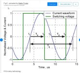
This tool creates a non-iterative but accurate LCC design tool that allows engineers to rapidly optimize their resonant tank parameters (series resonant inductance LS, series resonant capacitor CS, parallel resonant capacitor CP and transformer turns-ratio nTR) with given specified input/output electrical quantities and the desired magnetic component property.
Assumption of this tool
https://www.ti.com/lit/ug/tidt192/tidt192.pdf?ts=1702215797021&ref_url=https%3A%2F%2Fwww.ti.com%2Ftool%2FPMP22083
Assumption of this tool
- An PFC controlling the bus average voltage constant is in front of LCC.
- No magnetizing current. Z(Lm) is much bigger than the load impedance. >>>> Here
- Zero dead time of the half bridge.
- Zero transformer loss.
- Zero on-resistance of MOSFET and output diode.
- Zero dynamic resistance of LEDs.
https://www.ti.com/lit/ug/tidt192/tidt192.pdf?ts=1702215797021&ref_url=https%3A%2F%2Fwww.ti.com%2Ftool%2FPMP22083
Last edited:

Yes Oke, there are a lot of different stuff about it.
For as I did read, a LCC has Cp Cs and Lr this is where circulation current be,
and Cs/Cp = 1 or 0.1 depending of what wide regulation we want.
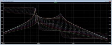
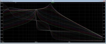
I have included a plot of the response of tank and transformer, If I use a small inductance in LCC
I get a extra resonance high in frequency, and to high load of the LCC tank, Cp is the one who
needs to do the trick, not the transformer who is just a isolation needed voltages.
The other plot is when I use inductance much higher as the Cp impedance, and lower that resonance
much below the working resonant points where it has to be.
I do talk about LCC?? I hope we have miscommunication about that? The LLC is a complete other thing
because here the transformer is a part of the resonance point and is indeed used for store circulation current
and if that inductance get wrong zvs will not occur. LCC has this circulation current into the resonance tank Lr
Cs and load cap Cp. We can include the transformer by put Cp on the secondary, I need that because of
I need high voltage, so have capacitance there in the windings I can use.
What concerns LLC you are right, the transformer is indeed a part of the whole tank, however I can just like
LLC can use a slotted bobbin for Lr using only Cp and Cs but is little harder to get right leakage therefore
a gap is used to trim, LCC needs no gap but maybe also need to adjust using one...
I admit I am not a professional in this, still learning and I did see when I follow the lessons, such simple technology
can be also very complicated.
Thanks by the way for the link, interesting.
regards
For as I did read, a LCC has Cp Cs and Lr this is where circulation current be,
and Cs/Cp = 1 or 0.1 depending of what wide regulation we want.
I have included a plot of the response of tank and transformer, If I use a small inductance in LCC
I get a extra resonance high in frequency, and to high load of the LCC tank, Cp is the one who
needs to do the trick, not the transformer who is just a isolation needed voltages.
The other plot is when I use inductance much higher as the Cp impedance, and lower that resonance
much below the working resonant points where it has to be.
I do talk about LCC?? I hope we have miscommunication about that? The LLC is a complete other thing
because here the transformer is a part of the resonance point and is indeed used for store circulation current
and if that inductance get wrong zvs will not occur. LCC has this circulation current into the resonance tank Lr
Cs and load cap Cp. We can include the transformer by put Cp on the secondary, I need that because of
I need high voltage, so have capacitance there in the windings I can use.
What concerns LLC you are right, the transformer is indeed a part of the whole tank, however I can just like
LLC can use a slotted bobbin for Lr using only Cp and Cs but is little harder to get right leakage therefore
a gap is used to trim, LCC needs no gap but maybe also need to adjust using one...
I admit I am not a professional in this, still learning and I did see when I follow the lessons, such simple technology
can be also very complicated.
Thanks by the way for the link, interesting.
regards
Attachments
Last edited:
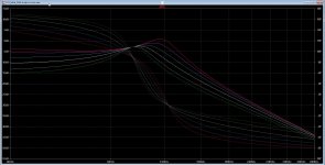
The LCL converter is also quite interesting, I did sim it and it can work fine without a load and still have zvs, but there is some higher circulation
currents lurking around, I have use M = 0.9 because under 1 vzs occur, above that zcs occur.
For audio amp supply purposes we need a fast regulating smps, open loop has higher output impedance's, also for LLC is this the case so
we are dependent of buffer elco,s like in normal supply.
LLC need a gap, these do not but can be used for adjustment purposes for transformer leakage.
here is LCL plot.
Attachments
Again, with no gap, there is not enough energy stored in the magnetizing inductance to achieve ZVS. One needs to balance both the dead time setting and the magnetizing inductance to achieve ZVS. Operating above resonance at a higher frequency just makes the situation worse. Where I work, it is standard procedure to park the operating frequency just below resonance. This is especially useful if you have an application like a battery charger or an LED driver that needs a considerable change in frequency to control the output current. A small amount of loss due to circulating current is better than operating all the time in hard switching. If you are looking at using an LLC converter to power an amplifier, it would be useful to set up the output to run in quasi-constant power mode, so that the output sags instead of going into full protection mode, which usually involves auto-restart. Having the converter parked slightly beow resonance maximizes the frequency excursion needed to retain control in constant power mode.
You are completely right, but I think we have here a discussion about two different resonance supply, I am busy with a LCC, that one
do not use the transformer inductance for zvs but the resonance tank, like series resonant do.
LLC do use the transformer as a resonance part and the gap is used for tuning because sometimes the windings primary are so low that
a gap is needed and has the same time advance for circulating current around for zvs, but there is a limit in that, to little circulating current and no zvs, to much cicrulating current and the parts like the resonant capacitor get to much voltage and current, but the same is in account for other resonant systems.
I use the LCC because I need high voltages also, soon I have a supply for tube amplifier, and now it is for hybrid.
LCC act as a constant current source to the transformer and as such this inductance Z need to be far from the full load resistance of the reflected load.
To get enough energy stored in LCC the Q is for full load around 1 and need slightly above that for to be sure for zvs, for light load the Q is above 1.6.
I have not simulate that and it works fine in sim, the signals are all oke. LCC allow for very light load but need a over voltage protection for open load, for this I use a sensor, a zener from the high voltage to the feedback already works fine, it cause the frequency to get high. But the chip has already also its own detection's.
regards
Attachments
Last edited:
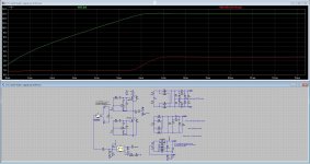
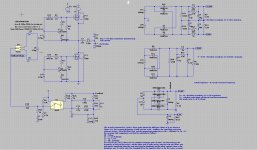
There is a problem I have to do yet, because when the 12 volt get regulated the open loop 350 volts and 2 x 120 is to low, I need to change the 12.6 6.3 outputs and lower the inductance so the voltage over the transformer rise, but maybe it is better to recalculate the locket transformer voltage who is then not 150 volts (half of input voltage) but get to 132 volts if supply is locked on 12.6 volts, so 132/350 = N 0.37 = (1/0.37squared)X primary inductance. (chooses for high Z what fit in transformer) and then it is right. or lower the 12.6 volts output inductance do work also, need more voltage from resonance tank, and nice it is a current source with the extra Cp capacitor so not more losses..
so I recalculate for new N for high voltages.
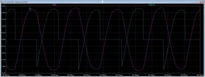
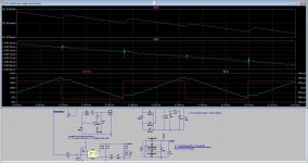
See pic of sims, I have recalculate the other open loop voltages after measure the transformer voltage on steady 12,6 volts what was 132 volts peak peak. And now I have the right voltages. but these change with load, not a problem with tubes. the sinusoidal signal has to be lagged on the square for zvs as seen on pictures.. I did lowering the 12,6 volt inductance where the transformer voltage did rise to above 150 volts peak peak, so as you see the current source works quite oke.
And the problem I have, and not yet know, is do I have to short all secondary transformer outputs for getting the leakage of the transformer? I have more then one
And now something completely different, the transformer gap as what this thread was about.
so I recalculate for new N for high voltages.
See pic of sims, I have recalculate the other open loop voltages after measure the transformer voltage on steady 12,6 volts what was 132 volts peak peak. And now I have the right voltages. but these change with load, not a problem with tubes. the sinusoidal signal has to be lagged on the square for zvs as seen on pictures.. I did lowering the 12,6 volt inductance where the transformer voltage did rise to above 150 volts peak peak, so as you see the current source works quite oke.
And the problem I have, and not yet know, is do I have to short all secondary transformer outputs for getting the leakage of the transformer? I have more then one
And now something completely different, the transformer gap as what this thread was about.
Attachments

Now we are talking LLC, I have try the system to see if it does also high voltages, it does.
I did get as low load as 100mA and still it does regulate.
different is also the LLC when do the N of transformer right, it is around resonance and has a nice clean sinusoidal
on the transformer.
No I ask myself, can I also do two transformers one for the regulated low voltage high current and one for the HV voltages,
only the high current is regulated and the other is open loop because for tubes 10 or 20 volts differences she don,t care about.
The LCC do also nice but it does pulsing into the transformer, that is because of the Cp capacitor where the circulating currents is twirling.
And something else when measure the leak in a transformer, do I need to short all the windings in secondary? or just one of them? I did
never ask but do now for sure, because I think just one needs shorted, the transformer has multiply output voltages.
I do calculate the two LCC outputs separately because that is needed to get it right.
thanks.
Attachments
Last edited:
When you measure the leakage, short both winding phases.
One other option for the high voltage output is to use a separate inductor to supply the leakage portion of the inductance. This inductor should be wound with Litz wire to avoid excessive losses, though relatively coarse Litz wire can be used. The transformer after this inductor can be wound with normal magnet wire, but needs a small gap to establish the proper magnetizing inductance. Basically the same rules apply for proper balance between magnetizing and leakage inductance, even though a separate inductor is used to supply the leakage.
The LLC converter is amenable to use of a voltage multiplier to get HV output. The simplest solution would be to use a voltage doubler. This is also a useful solution to provide +/- outputs for a solid state amplifier.
Last edited:
In case your secondary circuit consists of a tapped winding and two rectifier diodes I would measure primary stray inductance shorting only one half of the secondary winding.
I was thinking about my reply before, and we recommend winding with both phases of the transformer secondary winding twisted loosely together to promote symmetry between the two phases. Therefore it looks like bucks bunny is right, and you short one phase for the leakage measurement.
I would go as far as to say that you want to short each phase and measure the resulting leakage inductance. Winding both phases in parallel/simultaneously is often not sufficient to guarantee symmetry between the two operating phases, and you can get conditions where the resonant frequency varies between phases, so that one phase is operating above resonance and one is operating below - I have seen it quite often. Twisting the two secondary windings loosely together (a few turns per inch) helps to equalize the effective leakage inductance between the two operating phases and promotes symmetry. If you operate in voltage doubler or full-wave bridge mode, you can use a single winding, so you don't run into the phase symmetry issue. You have to deal with extra diode drops, so operating in voltage doubler or full-wave mode is recommended for higher output voltages where the extra voltage drop matters less.
I would go as far as to say that you want to short each phase and measure the resulting leakage inductance. Winding both phases in parallel/simultaneously is often not sufficient to guarantee symmetry between the two operating phases, and you can get conditions where the resonant frequency varies between phases, so that one phase is operating above resonance and one is operating below - I have seen it quite often. Twisting the two secondary windings loosely together (a few turns per inch) helps to equalize the effective leakage inductance between the two operating phases and promotes symmetry. If you operate in voltage doubler or full-wave bridge mode, you can use a single winding, so you don't run into the phase symmetry issue. You have to deal with extra diode drops, so operating in voltage doubler or full-wave mode is recommended for higher output voltages where the extra voltage drop matters less.
That is a long time ago, but I saw this coming by, the LCC do use a CS/CP capacitor, and a tank, this one do take care for zvs, circulating currenst go between this parts, low Q low inductance no zvs, except when have large CS, and a lot of loss, LCC is nice but calculation not., a LLC has a transformer/tank, or only transformer, with leak inductance there the circulation currents occur. Also here Q gain and such, all are much difficult to calculate, for me that is. But now I do understand more and there are tools.Wrong, wrong wrong.... If your magnetizing inductance is too high, you won't store enough energy during the course of a switching cycle to charge the stray capacitance of the switches and take advantage of ZVS operation. Hard switching will heat up your switches.
I have now in simulation a LLC and a LCC, last because I have a high voltage output for tube supply.
The LLC do also the high voltage quite oke.
Better ZVS in LCC.
regulation in current mode for fast response. Oke, I did see that calculating it is not that difficult, I can use the power transfer
equation only, and use a RLC calculator on google is all I need in fact. then simulate and watch the voltages
over the resonance capacitor and use a Q who satisfy the regulation from low to high.
FHA is here in the asc, if you want to examine things after the calculations.
Attachments
Sorry for going slightly off topic, but could you please elaborate on the different wire-types for xformer and external inductor?
As I understand it, its the same curent that circulates in xform in external inductor and I would assume there was similar demands on the the wire?
Kind regards TroelsM
As I understand it, its the same curent that circulates in xform in external inductor and I would assume there was similar demands on the the wire?
Kind regards TroelsM
The transformer after this inductor can be wound with normal magnet wire, but needs a small gap to establish the proper magnetizing inductance..
For lowest losses and frequencies between 50~100kHz litz wire with strands up to 0.1mm is your choice.
@bucks bunny: I understand that Litz is the go-to solution and accepted as "best solution for LLC", but Im curious on other opinions.
Litz may have some benefits, but I find it harder to source for a DI,Y and the copper-density is lower than normal copper-wire so conduction (for low freq?) should be higher?
The idea of using different wire for xform and external inductor was new to me.
Litz may have some benefits, but I find it harder to source for a DI,Y and the copper-density is lower than normal copper-wire so conduction (for low freq?) should be higher?
The idea of using different wire for xform and external inductor was new to me.
- Home
- Amplifiers
- Power Supplies
- LLC Converter maximum gap in core