hmmm maybe I will get a different trafo then!
EDIT: infact, i have loads of 2N5551's at home, so I will swap those first.
Be careful, 2N5551 is not the same component as the NC 5551 supplied with the L7 kit.
Probably has reversed connections.
This amp seems to work beautifully at lower voltages, but has random failures that need explanation. So I analyzed it. I noted a few issues and shared them from my perspective as an experienced engineer. The 1815s are an obvious issue, but I think the more serious problem is with the floating buffer shorting power and burning out, probably blowing the MOSFET gates and burning out speakers at the same time.
I like this amp, which I think is quite clever and they say sounds good -- when it works. It's just that it burns out randomly. There must be a reason for that, buried in the design details. My hope is to find some minor rework that cures the problem, and I think I have. Time will tell. I'm pretty sure the floating buffer parts explode when they short +- power without current limit. My fix is fairly easy, but it's only on paper and must be tested on a real amp. I should have parts soon and make the mods. Then I'll look forward to using this little gem.
Well, being not an engineer, I can speak only for my user experience. Once i used an L7 with a speaker that had part of the internal cabling in short circuit.
The amp kept playing even with a leg of the output mosfet that was incandescent. It kept playing until the component exploded with a big shot.
New drivers, one new output device and the amp was ready again to work as usual.
Anyway, let's keep the finger crossed for your mod to work in the best way, for safety and for sound as well.
I would like to connect it again to a 36-0-36 trafo and have it working properly. ;-)
Be careful, 2N5551 is not the same component as the NC 5551 supplied with the L7 kit.
Probably has reversed connections.
That is unlikely. The resulting confusion would be messy. I'd bet the pinout is typical EBC. To tell, use a DVM with diode setting and measure between pins. It should read about .55 v from base to emitter, and similar from collector to base. Reversed should be open. This test will confirm the pinout and is my quick check for shorts and opens in suspect parts, which seems to be 99.9% of failures.
For small signal parts, here are the most common pinouts found. Most American 2NXXXX transistors are EBC. Japanese 2SXXXX commonly use ECB. Europeans use CBE for many of the B series parts. There are exceptions, just to make you crazy. But you can bend leads on most parts to convert to the needed pinout of a board.
Power parts are almost always BCE, or GDS for MOSFETs, for good reason. The Collector or Drain gets hottest and is tied to the case for best cooling. Here are some exploded packages showing how the die is glued to the middle pin or collector in power packages.
https://s21.postimg.org/w2tvk2m2f/20160930_193553.jpg
I tell you my experience.
Like you, I expected that 2N 5551 and NC 5551 were just the same, but noticed the difference between them when my first pair of L7 had an amp that when hot began to crackle.
No way to resolve making all the solderings again.
So I purchased a new set of active components, apart the output devices, with 2N 5551, but after changing them it didn't work at all.
Tried to bend the pins from EBC to ECB, as you suggest, but with no results.
Then I asked my ebay seller to supply me some NC 5551 and then the amp worked again.
I tell you my experience.
Like you, I expected that 2N 5551 and NC 5551 were just the same, but noticed the difference between them when my first pair of L7 had an amp that when hot began to crackle.
No way to resolve making all the solderings again.
So I purchased a new set of active components, apart the output devices, with 2N 5551, but after changing them it didn't work at all.
Tried to bend the pins from EBC to ECB, as you suggest, but with no results.
Then I asked my ebay seller to supply me some NC 5551 and then the amp worked again.
I stand corrected. The designer had posted much earlier that the transistors are CC5551, not 2N5551. Makes life interesting, no? I googled for a data sheet, and apparently one maker is Continental Device India, LTD. Part is marked NCC5551 and has BCE pinouts according to their data sheet. Check it out here:
CC5551 pdf, CC5551 description, CC5551 datasheets, CC5551 view ::: ALLDATASHEET :::
Beware to anyone repairing this board, surprises await.

Great topic guys!
Any update on the improvements over the reliability and stability?
Recently output modules in my amp Optonica SM 7305 went south and with the output of original power supply +/-52 volts I found that this L7 kit might be a close replacement to the existing one (not the output modules, meant the whole output amps)
I understood that all transistors used at these voltages must have Vec (emitter-collector) more that 60 volts, ideally even more. Capacitors voltages of 63 volts would be enough?
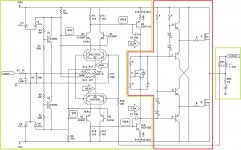
Also I wanted to ask if this hybrid schematics may have a chance to become a success - basically the portion marked in green is the original part of Optonica power amp, marked in red is the output stage from L7 amp that I hope to make friendly with the original input and mid stage.
Any thoughts and suggestions/reworks are really appreciated!
Any thoughts and suggestions/reworks are really appreciated!
Attachments
Poster asked:
No update. This seems to work OK up to +-40v. At 50 it cooks sometimes. To my knowledge nobody has done a fault analysis. Some parts in the input stage are only rated 50v Vceo, maybe that's a problem, but I don't think so.
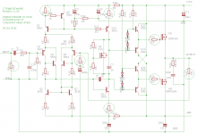
I suspect the output buffers fail and cause other damage. As you see, there is no emitter resistor on the output buffers. That means current is limited by internal resistance of the little buffer transistors, which is on the order of 15-20 ohms and the buffer runs off the total supply voltage when the output is pegged negative. That's risky for cross conduction of high current. This buffer is a standard sort of circuit for driving mosfets, but usually runs on 12v floating, not full supply voltage. If that is the problem (which we don't know), you could simply bypass the buffer. Or with modest rework, it could be made to work. IF that is the problem. As I said, nobody analyzed to root cause.
There is also something missing, zener diodes from the mosfet gate to source. The limit for voltage here is +-20v, and prudent designers always put back to back zeners here to limit it to say 12v. If the output wires are shorted, a common accident, then the gates see high voltages and will rupture the gate insulation and often short the devices. So that's another hole.
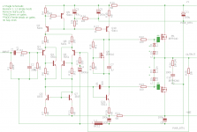
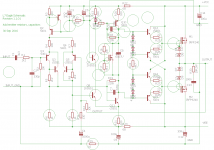
I will attach schematics, first original, second with the output buffer bypassed, the third patched a little. None have been built or proven, so use them as food for thought but don't assume they are known good.
Any update on the improvements over the reliability and stability?
Recently output modules in my amp Optonica SM 7305 went south and with the output of original power supply +/-52 volts I found that this L7 kit might be a close replacement to the existing one (not the output modules, meant the whole output amps)
I understood that all transistors used at these voltages must have Vec (emitter-collector) more that 60 volts, ideally even more. Capacitors voltages of 63 volts would be enough?
No update. This seems to work OK up to +-40v. At 50 it cooks sometimes. To my knowledge nobody has done a fault analysis. Some parts in the input stage are only rated 50v Vceo, maybe that's a problem, but I don't think so.
I suspect the output buffers fail and cause other damage. As you see, there is no emitter resistor on the output buffers. That means current is limited by internal resistance of the little buffer transistors, which is on the order of 15-20 ohms and the buffer runs off the total supply voltage when the output is pegged negative. That's risky for cross conduction of high current. This buffer is a standard sort of circuit for driving mosfets, but usually runs on 12v floating, not full supply voltage. If that is the problem (which we don't know), you could simply bypass the buffer. Or with modest rework, it could be made to work. IF that is the problem. As I said, nobody analyzed to root cause.
There is also something missing, zener diodes from the mosfet gate to source. The limit for voltage here is +-20v, and prudent designers always put back to back zeners here to limit it to say 12v. If the output wires are shorted, a common accident, then the gates see high voltages and will rupture the gate insulation and often short the devices. So that's another hole.
I will attach schematics, first original, second with the output buffer bypassed, the third patched a little. None have been built or proven, so use them as food for thought but don't assume they are known good.
Attachments
Limits on supply voltage
LJM, what are the limits on supply voltage? I have a regulated +/- 65 @ 1000VA. Is this too much?
LJM, what are the limits on supply voltage? I have a regulated +/- 65 @ 1000VA. Is this too much?

I changed my transformer and installed another smaller transformer for a speaker protection circuit I haven't built yet 🙂
This transformer is 30v which is giving me 45v dc. So much less than the 63v dc I used to have!
Why another transformer for speaker protection? You just need another bridge and capacitors, and lower the voltage to the one required on protection board.
Speaker prot
My experiments best demonstrate a separate secondary or small trafo (100~200 mA). The speaker protection usually uses AC voltage.
My experiments best demonstrate a separate secondary or small trafo (100~200 mA). The speaker protection usually uses AC voltage.
I have a +/-55v supply. My speakers are 4 ohm. Will this present a problem with the L-15D amps?
Also, I use a tube preamp that I like very much. Is there an easy way to reduce the gain on the L-15D so I can continue to use the preamp?
Thank you.
Also, I use a tube preamp that I like very much. Is there an easy way to reduce the gain on the L-15D so I can continue to use the preamp?
Thank you.
So it's not possible to share a single 36-0-36v transformer across two L15D-POWER boards? I have a 600VA 36-0-36 toroidal transformer and I was hoping I could feed two L15D-Power boards with it.
It seems to me that rectifiers feeding separate +/- voltage rails into separate boards shouldn't result in any forward biased diodes being in parallel even when they are sourced from the same secondary, so a situation where the entire current is carried by one diode because it has a lower forward drop voltage shouldn't arise. Though I am not an expert an can be missing something. Can you elaborate on why two L15D power boards cannot be connected to the same secondary?
It seems to me that rectifiers feeding separate +/- voltage rails into separate boards shouldn't result in any forward biased diodes being in parallel even when they are sourced from the same secondary, so a situation where the entire current is carried by one diode because it has a lower forward drop voltage shouldn't arise. Though I am not an expert an can be missing something. Can you elaborate on why two L15D power boards cannot be connected to the same secondary?
I temporarily does not provide L15D - PRO OSCON capacitance version.
Because the capacitance is not cheap, HA HA.
You may want to consider L15D - POWER ,But 2 stereo need 2 *transformer. AC 36-0-36
build the L7 for a active 2-ways speakers application.
On power ON, it give a loud bang from the speakers
So, a simple speakers relay protection is a MUST to protect it.
As for my subjective opinion, the amp sound very good. Go loud without fatigue.
And image very well too.
On power ON, it give a loud bang from the speakers
So, a simple speakers relay protection is a MUST to protect it.
As for my subjective opinion, the amp sound very good. Go loud without fatigue.
And image very well too.
Have you measured the DC offset of your unit?
If it's high, that might be the reason for the "bang".
DC offset should be corrected when it's high. The relays just protect your speaker, but offset is bad for sound.
If it's high, that might be the reason for the "bang".
DC offset should be corrected when it's high. The relays just protect your speaker, but offset is bad for sound.
the offset of all 4 amp are about 7 to 10mV DC.
The power to the amp are 36+/- VDC with 40,000uF to 2 amplifiers
I also have a thermistor at each of the transformer.
thanks
The power to the amp are 36+/- VDC with 40,000uF to 2 amplifiers
I also have a thermistor at each of the transformer.
thanks

the offset of all 4 amp are about 7 to 10mV DC.
The power to the amp are 36+/- VDC with 40,000uF to 2 amplifiers
I also have a thermistor at each of the transformer.
Besides the speaker protection, which you should install with or without thump,
you probably need a power soft start, with another relay. Something like this:
Class A Power Amplifier Soft Start Delay Temperature Protection Board 220V 30A | eBay
I don't think that thermistor is any help.
Look for threads on soft start in DIYAudio.
- Home
- Vendor's Bazaar
- LJM Audio