The 2092 is a bit fussy about how you connect it up.
I have blown up one by connecting one supply while switched on before another.
All supply lines must be turned on at the same time.
I also blew up another when connecting from a power supply still charged up.
I have blown up one by connecting one supply while switched on before another.
All supply lines must be turned on at the same time.
I also blew up another when connecting from a power supply still charged up.
I have a new board coming but now I check the voltage with no psu installed.
Tranny: 48.2 vac both sides.
After block rectifiers: 42.6 vdc both sides.
Why would this be?
Tranny: 48.2 vac both sides.
After block rectifiers: 42.6 vdc both sides.
Why would this be?
D
Deleted member 148505
I bought a L15-D Pro kit and soldered it. It was working very well. Dead quiet and sound was extremely well. Then I used it to drive my subwoofer.
Accidentally I interchanged the vcc and vee connections (I think) so it didn't work. Without noticing it I unplugged the power supply and connected another power supply which had two 10,000uf caps which already had charge.
I got a spark when connecting vcc (due to the stored charge in 10000uf caps)
I didn't care about that and connected all other connections and fired the amp.
All the speaker protection transistors caught fire. Later IRS2092 burned with smoke.
Now I'm waiting for the replacement parts to arrive from china (These ICs and Mosfets are not available in my country).
Does anyone know the possible reason why this happened?
How to avoid it in the future?
Thanks in advance 🙂
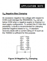
The IRS2092 was probably damaged when you connected the VCC first.
You should install negative bias clamping next time as suggested by AN1138.
Attachments
Hi ljm_ljm,
may i ask you to elaborate the differences between the L15D and the L15D-Pro boards? The obviously difference is the speaker protection of the L15D-Pro and the use of two IRF14019 instead of one IRF14019H. Are there advantages of doing so? Are both boards deliver a comparable sound quality?
Thanks
When I was in the design, is the hope L15D - PRO more comprehensive.
Because has the same performance as the IRFI4019 IRFB4019, can have a low distortion.
And have a larger current,
But I found that in practical test L15D - PRO moredistortion, very small.
Class D power amplifier test for the designer's experience, they are not you want to use better materials, can achieve better sound.
I don't insist on using IRFB4227, for example, because of its current is bigger, but the distortion will be large.
For home users. Distortion is always affect sound. While we may never use powerful power.
Need a lot of experiment class D amplifier. Until the test sample, we just know just how its performance and distortion.
And not only from the surface looks simple.
L15D L15D PRO - they are all conform to my request. But L15D performance better.
I bought a L15-D Pro kit and soldered it. It was working very well. Dead quiet and sound was extremely well. Then I used it to drive my subwoofer.
Accidentally I interchanged the vcc and vee connections (I think) so it didn't work. Without noticing it I unplugged the power supply and connected another power supply which had two 10,000uf caps which already had charge.
I got a spark when connecting vcc (due to the stored charge in 10000uf caps)
I didn't care about that and connected all other connections and fired the amp.
All the speaker protection transistors caught fire. Later IRS2092 burned with smoke.
Now I'm waiting for the replacement parts to arrive from china (These ICs and Mosfets are not available in my country).
Does anyone know the possible reason why this happened?
How to avoid it in the future?
Thanks in advance 🙂
I suggest that in any changes to the connection. After changes or parts. In the test.
In the input string of a light bulb. The above 110 v or 220 v voltage.
It can prevent damage. When our amplifier work, determine the right after installation.
We'll take the light bulb, this is the necessary safety measures.
Hope I won't appear the same problem.
Attachments
500-1000W 8 OHM L50 Full Bridge Amp
I've been thinking about for high power high performance amplifier. What way is the real meet demand.
It needs to accord with the real output power, rather than write letters we casually.
It needs very good reliability. I tried to use in this field about, L15, L12 field-effect tube, etc.
Customers and friends really need to use them, and feedback to me the information of sound.
I have prepared a long time, to choice all kinds of circuit, as well as the components of collocation.
It must be very simple, must be very reliable. And it must have a good voice.
The performance of the L50 may still not reached me. But this is my take a long time to answer.
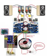
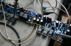
This is a photo.
I hope others can understand it.
It is composed of two identical amplifier. Each amplifier using two groups IRFP140 IRFP9140.
Because it requires a simple installation test, it is a tradition in L series has been.
Thus it integrates the speaker protection circuit, the use of two 12 a relay on two groups of amplifier dc output to conduct a comprehensive and reliable protection.
And it integrates the op-amp circuit level before. Former level gain for 5 times.
Former level jointly with the protection circuit using a set of AC12-0-12 v power supply. Using 7812 and 7812 voltage regulator IC.
Since L50 is made up by L15 circuit architecture, so its performance is the same with me.
It works very well. And has a good performance and reliability of any parameters.
I've been thinking about for high power high performance amplifier. What way is the real meet demand.
It needs to accord with the real output power, rather than write letters we casually.
It needs very good reliability. I tried to use in this field about, L15, L12 field-effect tube, etc.
Customers and friends really need to use them, and feedback to me the information of sound.
I have prepared a long time, to choice all kinds of circuit, as well as the components of collocation.
It must be very simple, must be very reliable. And it must have a good voice.
The performance of the L50 may still not reached me. But this is my take a long time to answer.
This is a photo.
I hope others can understand it.
It is composed of two identical amplifier. Each amplifier using two groups IRFP140 IRFP9140.
Because it requires a simple installation test, it is a tradition in L series has been.
Thus it integrates the speaker protection circuit, the use of two 12 a relay on two groups of amplifier dc output to conduct a comprehensive and reliable protection.
And it integrates the op-amp circuit level before. Former level gain for 5 times.
Former level jointly with the protection circuit using a set of AC12-0-12 v power supply. Using 7812 and 7812 voltage regulator IC.
Since L50 is made up by L15 circuit architecture, so its performance is the same with me.
It works very well. And has a good performance and reliability of any parameters.
Attachments
After the installation is complete,
I was tested for it.
Turn on the juice and we measure the voltage of power supply in the first place.
It is + - 54 v dc.
Then I measure separately the two amplifier amplification module, waveform.
Use double trace oscilloscope.
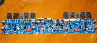
We can see. It works very well. And the two modules are the same.
This is because the two modules I used exactly the same components, as well as the PCB wiring.
Is completely COPY.
Why I didn't use the appearance more beautiful symmetrical component placement.
Because the two modules will produce the error.
I was tested for it.
Turn on the juice and we measure the voltage of power supply in the first place.
It is + - 54 v dc.
Then I measure separately the two amplifier amplification module, waveform.
Use double trace oscilloscope.
We can see. It works very well. And the two modules are the same.
This is because the two modules I used exactly the same components, as well as the PCB wiring.
Is completely COPY.
Why I didn't use the appearance more beautiful symmetrical component placement.
Because the two modules will produce the error.
Attachments


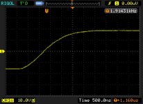
Because of using circuit is L15 L12 are using mature and reliable circuit. So the question is not big.
The waveform is very beautiful.
The SR in balance when can reach 38 v/US
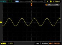
Important test. Measuring the first power supply voltage of the power amplifier. + - 54 v.
And then increase the signal input.
The signal input is: 800 mv
The waveform is very beautiful.
The SR in balance when can reach 38 v/US
Important test. Measuring the first power supply voltage of the power amplifier. + - 54 v.
And then increase the signal input.
The signal input is: 800 mv
Attachments
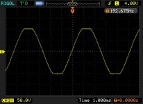
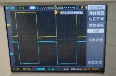
We rotate the signal amplitude, let him work in distortionless condition.
A little bit to reduce signal. At this point about 0.8 V input. The output 100 v
VOLTAGE GAIN =125
About power can be calculated. About 610 w 8 OHM
A little bit to reduce signal. At this point about 0.8 V input. The output 100 v
VOLTAGE GAIN =125
About power can be calculated. About 610 w 8 OHM
Attachments

Last edited:
I will continue to test this L50, improvement.
So temporarily won't have sales on the Internet. Anyone is welcome to give directions.
I would have taken the time to put on the updated information. I hope it can let more people inspired.
I think the class AB amplifier than class D amplifier is more suitable for the application of professional.
It has better reliability. And it has a good performance.
It is better than digital amplifier with low frequency. Can work at 10 HZ or 100 k HZ
It is a real 500 w amplifier 8 ohms.
Rather than just write the Numbers. It works at + - 50 v voltage can satisfy the requirement of 500 w power output.
For the majority of users, can be satisfied.
Last edited:
I have replaced the faulty parts and powered up the amp. 5551 transistors caught fire as before. Replaced them again and powered the amp. sane thing happened. Can you point me out where the actual problem resides? Please help
I have found the 2092 is often taken out when the mosfets go.
The mosfets just blow again straight away.
As others have said a light bulb in series with mains is a good way to go.
The mosfets just blow again straight away.
As others have said a light bulb in series with mains is a good way to go.
Quote
Accidentally I interchanged the vcc and vee connections (I think) so it didn't work. Without noticing it I unplugged the power supply and connected another power supply which had two 10,000uf caps which already had charge.
Unquote.
I messed up a 2092 amp when I connected the rails one at a time with croc clips.
The power supply was still charged up and blew the mosfets and 2092.
Hello nigelwright7557!
Thank you very much for your help. It seems like almost all the zener diodes have become faulty. I think it happened because I interchanged the vcc and vee 🙁
I can find IN4148 zener diodes easily so is it possible to replace 5v6 and 15v zener diodes with IN4148s? Also do you have any idea about the other faulty items which caused by the interchange of vcc and vee. I'm going to change both mosfets and irs2092.
Update:
I got the speaker protection part working (atleast the relay works) but the blue led doesn't come on. Connected a speaker and I can barely hear continuous pops from the speaker.
(Replaced a 5v6 zener diode with IN4148 and a 15v zener diode with a IN4148 zener diode)
Hello nigelwright7557!
Thank you very much for your help. It seems like almost all the zener diodes have become faulty. I think it happened because I interchanged the vcc and vee 🙁
I can find IN4148 zener diodes easily so is it possible to replace 5v6 and 15v zener diodes with IN4148s? Also do you have any idea about the other faulty items which caused by the interchange of vcc and vee. I'm going to change both mosfets and irs2092.
Update:
I got the speaker protection part working (atleast the relay works) but the blue led doesn't come on. Connected a speaker and I can barely hear continuous pops from the speaker.
(Replaced a 5v6 zener diode with IN4148 and a 15v zener diode with a IN4148 zener diode)
1N4148 is NOT a zener diode 😱
If you reverse VCC and VEE your board is fried , buy a new one !
Cheers ,
Rens
- Home
- Vendor's Bazaar
- LJM Audio