Lisoformio ( very strange nick)
please wake up 🙂
4) the winding schemes are different
from post 58
It is normal that the space is different between the wire because the wire are different; a kid of three years old can understand this but the architecture is the same.
Walter
A three years old kid should use 1) the SAME CORE and 2) IDENTICAL WINDING GEOMETRY on IDENTICAL BOBBINS.
Last edited:

Is very difficult to see the tests related ONLY to a O.T trafo; we think that the test set we propose is, at the moment, the best one available.
Every suggestion is welcome, of course.
I am working, with Fabrizio, to understand how much is better the Litz ot Trafo or is not convenient to build it under the costs/performances aspect .
We think that Litz is better for a simple reason ( just to tell one) because the point of resonance is moved at higher frequency.
But we have, with next prototype, to have a better L at low frequencies; soon I have to test a new one that is coming for a s.e. project.
OK here my suggestion:
1. Design the output transformer for a well known application, for example SE 300B; this means there must be some 25 H of primary induction, airgap to allow 70-80 mA primary DC current; winding ratio 20:1 (3k2:8R); choose double c-core.
2. Wind two coils with litz wire to make a stereo set of output transformers;
3. Wind another two coils with magnet wire for another stereo set of output transformers;
4. Litz wire and magnet wire coils should have the same number of turns in order to have the same primary induction, and the winding technique (number of primary and secondary sections, interleaving, winding space) should be the same. So, as stated before, this will give lower DC resistances for the magnet wire coils, less insertion loss and lower output impedance of the amplifier;
5. Assemble the two pairs, and invite friends to do a well set up DBT with the transformers in the 300B amp, driving appropriate loudspeakers.
Last edited by a moderator:
Pieter
I confirm that the difference on Rdc between the two coils aren't significative; this is possible to demonstrate also on the labs.
For s.e. I always use 6 ohm on secondary , any tap.
The ratio is 20:1.
As told you I am waiting other trafo.
Walter
I confirm that the difference on Rdc between the two coils aren't significative; this is possible to demonstrate also on the labs.
For s.e. I always use 6 ohm on secondary , any tap.
The ratio is 20:1.
As told you I am waiting other trafo.
Walter
x Lisoformio
Please try to read again the post 1 fig. 5.
If you carefully look on the curves of both versions you can see that until the resonance the shape is similar so the impedance is increasing because L is increasing with frequencies, as normal.
After the resonance the capacitive component became significative and the impedance goes down; in this case the quality ( or the type) of the core is not so important as these parasitic components, of course I mean that we always using a reasonable good stuff as magnetic core.
In this case is most important the architecture of the winding because so you can have less losses.
This as general aspect.
In my opinion, if you look at fig. 3 post 4, what I must have to do better is to reach an higher L so at low frequencies I will have less distortion and the new stuff I am waiting goes in this direction.
For high frequencies I am sure about the way to follow.
The diagram I have posted aren't easy to find as real test on trafo; the program that Fabrizio is developping ( fig. 3 post 4) is under test and I don't know when it will be available; it is very smart.
Last edited:
In addition
If you look at fig. 3 post 4, THD vs freq. we can see that the shape of distortion on low frequencies are similar, less or more.
At high frequencies on normal wire the curves tend to have a kink ( around 5K, close to res. freq.) then tend to go up around 20 kHz ( just a little ); on Litz the kink is less and the curves are incresing less until 20 kHz .
Walter
Until you have two transformers, litz and normal, with the same parameters, your measurements and conclusions are completely meaningless.
You already suggested in post 4 that you are awaiting a new prototype with more primary L, but nevertheless you continue to compare apples with oranges....
You already suggested in post 4 that you are awaiting a new prototype with more primary L, but nevertheless you continue to compare apples with oranges....
I am not agree.
I sent post nr. 67
Please let me know if you are agree or not on what I wrote.
In addition, please read post 4 and fig. 4
if you have to decide which trafo you must to buy which is your choice? the one with a resonance at 60 kHz (and second at 120 khz) or the other with 105 khz (second at 160 khz)?
note: on fig. 2 there are the freq. respnse, the differences are consistent
Thx
Walter
Last edited:
These are some diagram:
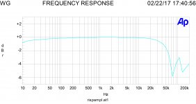
1- freq. answer s.e. with KT88 in triode, driven by ECC81, Litz trafo, no FB
good bandwidht, - 2 dB at 50 kHz; at 8 watt same but at low freq. I lost 1 dB at 20 Hz, not so bad.
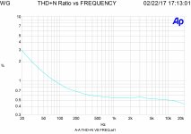
2- thd vs frequency
very good perf but at low frequency I hope to do better
It is a simple project , about 8 watt with 2% at 1khz
Walter
1- freq. answer s.e. with KT88 in triode, driven by ECC81, Litz trafo, no FB
good bandwidht, - 2 dB at 50 kHz; at 8 watt same but at low freq. I lost 1 dB at 20 Hz, not so bad.
2- thd vs frequency
very good perf but at low frequency I hope to do better
It is a simple project , about 8 watt with 2% at 1khz
Walter
Attachments
Last edited:
Gentlemen,
I read this thread over several days, and am not now going to go through it all again in case I missed some minor detail.
With that proviso, I detected that much of the argument is over practical details vs. theory. Let me then on that presumption immediately ask: Has anybody ever wound several models of the same data? If so you would have realised that even with attention to detail (and layer-winding for better consistency), a normal spread in results can be up to 10%, particularly at h.f. Exact distance between sections etc. is hard to maintain with stiff wire (secondary) and has a direct effect on leakage reactance and interlayer/intersection capacitance. (My experience over several sets of up to 10 transformers, not one or two.)
Also, I detect 'raised temperatures' between members. It doesn't help science and professionalism to be hurt by comments. Suggestions were invited, and human beings are not good measuring and expressive instruments. Yet we get good results by trying to stay objective. (In this respect folks will have to kindly excuse me when I say that in audio hearing tests as arbiter between not too different several components are simply out - it is, comparatively, the worst "measuring instrument" one can get. Just in passing ....)
I accept all that is intended by the gentlemen running these tests and am standing by for completion of the same, but they must in turn understand that basic electronics as proven a multitude of times, cannot simply be wiped aside because a one-off experiment seems to indicate so. (Here I rather frowned at the utterance that RDH is ancient. Please folks ...) If such an indication apprears to be the case (and in my life as a researcher it happened with unnerving regularity! ) one has to look elsewhere than simply accepting that a basic principle is no longer valid or is not valid in the case under discussion. In this case I am referring to the established fact that Litz-wire has little/no effect on anything at frequencies below say 200 KHz - that naturally, apart from the influence the wire geometry might have.
I will when convenient go back to the nice graphs presented, but let us in the meantime care not to violate experimental protocol too much.
P.S: Waltube,
I compiled the above before noting your last post immediately prior to mine.
I read this thread over several days, and am not now going to go through it all again in case I missed some minor detail.
With that proviso, I detected that much of the argument is over practical details vs. theory. Let me then on that presumption immediately ask: Has anybody ever wound several models of the same data? If so you would have realised that even with attention to detail (and layer-winding for better consistency), a normal spread in results can be up to 10%, particularly at h.f. Exact distance between sections etc. is hard to maintain with stiff wire (secondary) and has a direct effect on leakage reactance and interlayer/intersection capacitance. (My experience over several sets of up to 10 transformers, not one or two.)
Also, I detect 'raised temperatures' between members. It doesn't help science and professionalism to be hurt by comments. Suggestions were invited, and human beings are not good measuring and expressive instruments. Yet we get good results by trying to stay objective. (In this respect folks will have to kindly excuse me when I say that in audio hearing tests as arbiter between not too different several components are simply out - it is, comparatively, the worst "measuring instrument" one can get. Just in passing ....)
I accept all that is intended by the gentlemen running these tests and am standing by for completion of the same, but they must in turn understand that basic electronics as proven a multitude of times, cannot simply be wiped aside because a one-off experiment seems to indicate so. (Here I rather frowned at the utterance that RDH is ancient. Please folks ...) If such an indication apprears to be the case (and in my life as a researcher it happened with unnerving regularity!
) one has to look elsewhere than simply accepting that a basic principle is no longer valid or is not valid in the case under discussion. In this case I am referring to the established fact that Litz-wire has little/no effect on anything at frequencies below say 200 KHz - that naturally, apart from the influence the wire geometry might have.I will when convenient go back to the nice graphs presented, but let us in the meantime care not to violate experimental protocol too much.
P.S: Waltube,
I compiled the above before noting your last post immediately prior to mine.
Last edited:
Hi Johan
I have to read you post carefully due my italian/english.
Tomorrow morning I take time to read it.
Now are the 1,30 in the night.
Good night to everyone
Walter
I have to read you post carefully due my italian/english.
Tomorrow morning I take time to read it.
Now are the 1,30 in the night.
Good night to everyone
Walter
Seeing here
http://www.diyaudio.com/forums/tubes-valves/264337-o-t-litz-wire.html
And here
GM70 amplifier with Fiat transformers
I can conclude that you are Walter Gentilucci from FIAT SRL, a transformer manufacturer, and this thread is about promoting your transformers, wrong place...
You cheated us! 😡
http://www.diyaudio.com/forums/tubes-valves/264337-o-t-litz-wire.html
And here
GM70 amplifier with Fiat transformers
I can conclude that you are Walter Gentilucci from FIAT SRL, a transformer manufacturer, and this thread is about promoting your transformers, wrong place...
You cheated us! 😡
Seeing here
http://www.diyaudio.com/forums/tubes-valves/264337-o-t-litz-wire.html
And here
GM70 amplifier with Fiat transformers
I can conclude that you are Walter Gentilucci from FIAT SRL, a transformer manufacturer, and this thread is about promoting your transformers, wrong place...
You cheated us! 😡
No problem with promoting transformers.
No need to accuse fellow members being cheaters.
When you have problems with it, report to moderation.
When it is about promoting, ask moderation to move the thread to the appropriate forum.
No problem with promoting transformers.
There is one real problem, with promoting snake oil. And it is a HUGE problem.
When it is about promoting, ask moderation to move the thread to the appropriate forum.
Do we have a "Snake oil promotion forum"?
the McIntosh MC275 OPT's used just one size wire, then paralleled multiple strands to get the desired ampacity......if this is not Litz, tell me...http://www.merrenaudio.com/mcintosh
No problem with promoting transformers.
No need to accuse fellow members being cheaters.
When you have problems with it, report to moderation.
When it is about promoting, ask moderation to move the thread to the appropriate forum.
From the first post this thread is full of inconsistencies, from the first picture both transformer bobbins do not match dimensionally, subsequent puzzling posts... contradictions...
If accusing someone of cheated us seems insulting and offending, please accept my apologies, but seems to me that his was not a correct attitude to say the least.
Without all those issues this would be just another good technical discussion.
Ah, by the way, do not count on me to being a snitch...
Last edited:
Can anybody believe that a transformer manufacturer can not perform a clean experiment winding 2 identical transformers by different wires on the same bobbin and iron, with the same layers and numbers of turns?
I don't. And his claim about capacitances is misleading, as all other arguments.
Speaking of McIntosh, bi-filar, tri-filar and so on windings don't mean "litzendrate" usage. It means just 2,3, or more identical windings, with minimal possible stray inductance.
McIntosh had a crazy idea about so deep cathode feedback so they had to use bootstrap of driver stages that is a positive feedback by voltage that reflects all errors of the output stage back to the driver. Was it worth it? Absolutely not, but it was "novel", "special", "recognizable". Just a marketing approach.
Should we consider it a best practice valuable for DIY?
I don't think so.
Should we consider it a best practice valuable for DIY?
I don't think so.
agreed....with tubes, i found that the simplest of circuits can truly amaze...
- Status
- Not open for further replies.
- Home
- Amplifiers
- Tubes / Valves
- LITZ output trafo