Hi there, foumd this old thread. I just received the mv02, but i dont know how to hook things up. Can anyone help me out?
do you have the relevant instructions or the mv02 arrived without?
Hello!
I am trying to put one MV-06 together to be able to send audio from different sources to my active speakers.
When I was plugging the power in, the R21 resister started smoking. Since I am a noob and don't read schematics very well, can anyone for starters help me and tell me that resistors function. I would be for ever grateful.
Thanks to this thread. I used it to work my out MV-06 remote, which of course has only 5 different positions! That's all I wanted anyway, so it all seems to work, at least on the breadboard, even the 5 LEDs, once I realised the switching was done on the negatives!
Well, I thought I had it working OK, but although relays 1-4 work as expected, 4 stays closed when 5&6 are activated! So at the moment I can have 4 separate inputs, but not 5.
Bummer. I've lost the will at the moment, but I'll turn the board over and check everything for shorts, etc, when I can face it again. 😡
Bummer. I've lost the will at the moment, but I'll turn the board over and check everything for shorts, etc, when I can face it again. 😡
Just in case anyone is interested, I found a workaround. Take the signal output from relay 4 through the normally closed pins on relay 6, back to the output pins of 4, and then when 5 and 6 are switched on the signal from 4 is cut. Relay 4 stays on, but the signal goes nowhere.
Just in case anyone is interested, I found a workaround. Take the signal output from relay 4 through the normally closed pins on relay 6, back to the output pins of 4, and then when 5 and 6 are switched on the signal from 4 is cut. Relay 4 stays on, but the signal goes nowhere.
Had the same problem, but i though it was pcb problem.
Any schematic (even a draft)?
Thanks!
Anyway, here's a scan of the modified schematic. Cut the PCB to the sockets to channel 4, and run the signal through relay 6. When relay 4 closes, the signal runs through relay 6 to the normally open pins, completing the circuit to outputs 4. When relay 6 turns on it breaks the link to 4.

Of your modification!Do you mean a schematic of the whole kit, or of my modification?
(Sorry for the delayed answer)
Here's a pic of the relay. You can see which pins are normally closed. Use those on relay 6 for the output from relay 4.
http://www.diyaudio.com/forums/attachment.php?attachmentid=515183&stc=1&d=1447853510
http://www.diyaudio.com/forums/attachment.php?attachmentid=515183&stc=1&d=1447853510
Attachments
I should have said normally closed; the unconnected pins.Anyway, here's a scan of the modified schematic. Cut the PCB to the sockets to channel 4, and run the signal through relay 6. When relay 4 closes, the signal runs through relay 6 to the normally open pins, completing the circuit to outputs 4. When relay 6 turns on it breaks the link to 4.
View attachment 515097
I should have said normally closed; the unconnected pins.
Explained on this?

Attachments
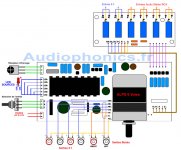
Not really. That shows how everything is connected, but doesn't tell you how to turn off relay 4 when 5 is on. I am using the kit to control an LDR attenuator, so only use one channel of each relay, and don't want several relays switching together. There is no audio signal running through the volume control and relays, just the control voltage for the LEDs in the LDRs.Explained on this?
 This shows 3 inputs; I have 5.
Not really. That shows how everything is connected, but doesn't tell you how to turn off relay 4 when 5 is on. I am using the kit to control an LDR attenuator, so only use one channel of each relay, and don't want several relays switching together. There is no audio signal running through the volume control and relays, just the control voltage for the LEDs in the LDRs.
View attachment 515207 This shows 3 inputs; I have 5.
I am planning to use it for multiple sources (tape/pickup/FM-radio/e.t.c) but my draft build shows only 4 sources (as you confirmed).
On my above sketch, how do you connect them?
Can't do it using your sketch. You have to follow my modified schematic, cutting traces and linking relays. Then use inputs 1-5.
Last edited:
Oh, and link L to FC, and R to RC on the relay board. And use outputs RIGHT and LEFT on the main board. I think!
And it works! 5 separate inputs and volume control. It's just a pity there is no English schematic.
- Status
- Not open for further replies.
- Home
- Design & Build
- Parts
- Lite Audio MV-01 / MV-06 remote controlled volume/input selector