I appreciate that @Abraxalito is doing the engineering and staying away from the alchemy part of it. It is better to tweak a good design by adding the confounding variables then build a design around confounding variables.
So here are some variables, make of them what you will.
Muse ES 1000uf on the power in makes the music feel like you are on the tail end of a magic mushroom trip where everything is still not quite synced to reality. It is really fun though.
Nichicon HW 3300uf, very smooth top end, easy to listen to but maybe too smooth? Definitely not offensive and actually really good, but I prefer a bit more sparkle.
Silmic 470uf, damn thats good.
All sound different, but playing with the pixie dust is not a way to design a DAC.
Use a dvm to measure voltage of ES cap though bi polar you'll notice 1 leg will have negative reading. If the PS is a positive rail connect the neg reading leads of ES to the positive rail & the other to ground & listen again.
Use a dvm to measure voltage of ES cap though bi polar you'll notice 1 leg will have negative reading. If the PS is a positive rail connect the neg reading leads of ES to the positive rail & the other to ground & listen again.
Ok, I measured it and found the negative leg and tested a few times back and forth. There is a small difference with it being better the way you recommended, however, the sonic signature of the Muse ES is still unique.
I did not want my previous post to indicate that it sounded bad, quite the opposite. It sucks you in and is full and lush and energetic but it makes me feel like I smoked a joint and I get lost in the music. I am not complaining, I just cant seem to do Excel work while listening to this combo.
The Silmic also sounds great. The Muse ES is psychedelic and the Silmic more alcoholic if that makes any sense at all.
I guess I will leave the Muse ES in there and call it the PSYdac 🙂
Last edited:
the thing about all this tweaking is that it distracts from what I perceive to be the biggest improvements, topology, layout, chips/semis etc. I know it all matters, but I prefer to focus on a new dac, or amp than swapping caps. Having said that, I have had lots of fun tweaking CD players too🙂 Just too much stuff to try on limited time and money.
Tweaking for me is the final part of geting the sound that Im looking for Luke, hence my comment about buying a properly design kit in the first place. Even now that my dac is fully optimized for for set up, at times I do wonder what if ???? but then it'll never end. lol
I'm forever wondering 'what if?'..... 😀
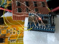
Incidentally, here's the first incarnation of the I2S slower. There's an S/PDIF interface (yellow PCB underneath), the interface logic from I2S to SPI (on the red board) and the Taobao F030 module (blue). My wife listened to the effect on both GrossDAC and PhiDAC Quad - she said it lost some rhythmic drive (but gained some kind of druggy floatiness) on PhiDAC but didn't notice the former effect on GrossDAC.
Today I'm going to re-write the software for the new CPU which has one real I2S interface, its only half-duplex though so the SPI interface is still needed for input. I think it won't need as many logic ICs though overall.
Attachments
Last edited:
Ok, I measured it and found the negative leg and tested a few times back and forth. There is a small difference with it being better the way you recommended, however, the sonic signature of the Muse ES is still unique.
I did not want my previous post to indicate that it sounded bad, quite the opposite. It sucks you in and is full and lush and energetic but it makes me feel like I smoked a joint and I get lost in the music. I am not complaining, I just cant seem to do Excel work while listening to this combo.
The Silmic also sounds great. The Muse ES is psychedelic and the Silmic more alcoholic if that makes any sense at all.
I guess I will leave the Muse ES in there and call it the PSYdac 🙂
The ES caps makes presentation wider/bigger but highs not very good hence when you use it the way that I mentioned, highs & mids etc becomes clearer.
As for Silmic ll I don't know what the hype is all about, tested it in so many locations. The only good thing about it is mids sound tubey, bass tubby no slam compared to KZ, highs very artificial, try lstening to cymbals & hi hats you understand. There's a Japanese market only Silmic ll, aah this not bad much less evil.
Richard,
I've been reading your Hackaday blog and am interested in building the SE. I'm certainly interested in an SE kit. If there still not enough interest, then that's fine, I will still proceed.
My I/V of choice is always discrete follows by a cathode.
Has anyone here done this type of OPS.
Great work and I'm also reading your parallel thread.
Cheers,
Greg
It is worth increasing resolution even so small as to 18-bit, but I it is a level of complication which gives grounds for another project, I absolutely agree.As for 122dB - well its a noise level which makes sense for 20bit input material. I don't think I have any as pretty much all I have is RBCD. But I like the challenge of getting there. The idea can go the other way too - I have some 'industrial' 12bit DACs sitting in my intray, I'd like to build an array of them to give 16bit performance.
A note to all others who are not aware yet: quantization noise (perceived as harshness) is also reduced by increasing sampling rate. It is confirmed that Gross DAC can be sampled at least 96kHz, but my goal would be 196kHz. It may be achieved straight away or by halving number DAC chips - will see.
With modern technologies perceived bit depth is also increased the other way. First CD's were sounding very harsh, but for number of years CD's are mastering with dithering. Why? This is because dithering increase dynamic range by 6dB (from 96 to 102). When applying noise shaping, it can further increase to 120dB, typical is 115dB. It is very close to the undithered 20-bit material. In other words, we don't have to concern about 16-bit resolution in PhiDAC or Gross DAC at all.
I was very excited when hearing about @abraxalito heading to include microprocessor in the project. This can bring a foundation for standalone devices, network streamers, etc... In our case processor can apply dithering when incoming bith depth is greater than 16-bit. I do apply dithering currently on a Foobar when playing on my R2R DAC (16-bit of course), but there is no way in Foobar to not dither 16-bit source when this option is enabled. Having it implemented in a DAC would save a trouble. Or even upsampling. I remember first device doing upsampling the right way: ECD 1
– International
I do apologize to the @abraxalito and others for my part in inductors story, it wasn't deliberate. Lets focus now on important things. 🙂
Last edited:
A note to all others who are not aware yet: quantization noise (perceived as harshness) is also reduced by increasing sampling rate.
Do you have a link which confirms this as a fact (maybe with some math)? I'm aware that oversampling in conjunction with noise shaping can push quantization noise out of the audio band. That's how Philips was able to use a 14bit DAC to get close to 16bit performance in their first CD players. In theory the quantization noise from a DAC is spread out over the full bandwidth so by only using half of the band and band-limiting hard there should be a reduction but that's assuming all the additionally introduced (interpolated) samples don't introduce more quantization noise. In reality they do as typically they're not going to fall on precise 16bit values. Or put another way, the new samples are calculated at more than 16bit precision and need to be truncated/rounded/dithered to output them on a 16bit DAC.
Any link to confirm this? In my understanding dither is to improve linearity, not to increase dynamic range. A system without dither isn't linear, most noticeable at low signal levels where quantization distortion is generated. Adding dither turns the distortion into noise, so long as the PDF of the dither is correctly chosen (TPDF). A TPDF dithered 16bit system has something like 92dB of dynamic range.With modern technologies perceived bit depth is also increased the other way. First CD's were sounding very harsh, but for number of years CD's are mastering with dithering. Why? This is because dithering increase dynamic range by 6dB (from 96 to 102).
Noise shaping by itself won't help, it needs oversampling to give some space in the spectrum to move the noise to. True that noise-shaped dither can give a perceptive improvement in the SNR but the measured number will be poorer. The problem with noise-shaped dither is it needs a flat FR - if anything in your system introduces some EQ (intentionally or not) then you may end up with a very strange-sounding noise floor. I prefer to keep away from such tricks myself.When applying noise shaping, it can further increase to 120dB, typical is 115dB. It is very close to the undithered 20-bit material. In other words, we don't have to concern about 16-bit resolution in PhiDAC or Gross DAC at all.
I'm not planning to introduce such complex MCUs as those having network interfaces. That seems like a step too far to me at present, but I'm not completely ruling it out in the distant future.I was very excited when hearing about @abraxalito heading to include microprocessor in the project. This can bring a foundation for standalone devices, network streamers, etc...
Greg- thanks for your interest, no PhiDAC SE kits have been created. I still plan to make kits for PhiDAC Quad in the future, also for grossDAC once things here return to some semblance of normality.
Last edited:
It has nothing to do with oversampling. If you draw a graph of the sample value (Y) versus time (X), you will see how simple it works. Increasing number of levels (bit depth) on the axis Y reduce error of the value. I am sure you agree with. The same happens on axis X. When you probe more frequent, horizontal precision is increasing. The real value of the sample is positioned somewhere between measured X and Y. Or in other words error in X can be calculated to the error in Y and in reverse, depends how you look at...Do you have a link which confirms this as a fact (maybe with some math)? I'm aware that oversampling in conjunction with noise shaping can push quantization noise out of the audio band. That's how Philips was able to use a 14bit DAC to get close to 16bit performance in their first CD players.
It is a concept of seeing (or hearing in this case) below a noise level. It is correct that a noise level is increasing, so by dithering a real dynamic range is reduced to roughly 92dB. It is how we measure it, but DSP processing can remove uncorrelated noise out of the original stream (clean it up). When we see measurement graphs of DACs with a floor noise level -140dB, these are for sure a specially DSP prepared graphs to show what happens below noise level. The same happens in our brain. By dithering noise is increasing, but we can pickup details below 16-bit resolution, so perceived dynamic range is increasing.Any link to confirm this? In my understanding dither is to improve linearity, not to increase dynamic range. A system without dither isn't linear, most noticeable at low signal levels where quantization distortion is generated. Adding dither turns the distortion into noise, so long as the PDF of the dither is correctly chosen (TPDF). A TPDF dithered 16bit system has something like 92dB of dynamic range.
This phenomenon is frequently demonstrated the following way: Place a comb horizontally before your eyes, keep it steady and look through at some object. You can see some areas sharp, but other areas are completely obscured, completely lost. Them move a comb left and right, you can see the all picture, less sharp but consistent.
Regarding numbers, I am sure there are correct, will post links later. Reading this material will clear out your other questions.
Last edited:
It has nothing to do with oversampling.
Ah but my example did have a whole lot to do with oversampling. Your example seems to include an ADC which samples faster too, in which case I agree - you get lower noise in the audio band as the quantization noise is spread out over a wider bandwidth. If your recording is 88k2 or 176k4 then it makes sense to play that back at the recorded rate. But with a recording at 44k1 no lower noise results from playing that back any faster.
It is a concept of seeing (or hearing in this case) below a noise level.
Yes using dither allows a listener to hear into the noise. So even a -144dB level sinewave gets reproduced correctly (assuming perfect DAC) when dither is used. Can't follow most of the rest of what you said.
An FFT with a 'grass' level of (say) -140dB isn't an integrated-over-the-audio-band figure, rather just the level in one very narrow bandpass filter. Its a very common mistake to make. Also perceived dynamic range is rather a different thing from dynamic range. The latter being measured so can be quantified - your figure of 102dB isn't one that anyone I've seen has measured from a 16bit system.
Another common mistake. It is not filtering it is averaging. You set such parameter on your analyser doing FFT transform when testing response to the static (say) 1kHz signal. It allows you to see clearly on the display what happens below noise level. It doesn't work well on a dynamic signal, but our brain can do better.An FFT with a 'grass' level of (say) -140dB isn't an integrated-over-the-audio-band figure, rather just the level in one very narrow bandpass filter. Its a very common mistake to make.
The perceived dynamic range is all we are concern about. It is how our brain hear sounds. It is not true that it cannot be measured. It can be measured by using a static hi-res sine test signal and dither it before converting to the 16-bit resolution at different volumes. Then FFT analyzer will tell you result. It will confirm theoretical 102dB resolution from 16-bit. Everything above (up to 120dB) is in result of applying noise shaping to the dither. Yes, from this moment we can talk about filtering.Also perceived dynamic range is rather a different thing from dynamic range. The latter being measured so can be quantified - your figure of 102dB isn't one that anyone I've seen has measured from a 16bit system.
I am running out of my cellular data allocation now, so I am giving up on finding links for you, Wikipedia is a good start: Dither - Wikipedia
Another common mistake. It is not filtering it is averaging.
Having used an AP in a couple of my previous jobs I can categorically say this is certainly wrong. Yes, its possible to set averaging but that's separate from the FFT. Averaging reduces the variation between the bins, giving a smoother layer of 'grass'. What allows the FFT to show components beneath the full-bandwidth noise level is it acts as an array of bandpass filters, each with narrow bandwidth.
Back to the 'Queen's English' again are we?The perceived dynamic range is all we are concern about.
<snip technical-sounding blah>
I'm getting deja-vu, this is highly reminiscent of the inductors saga.
I can't follow you on this, sorry, it is not productive. I want you to focus on the project and I do support it wholeheartedly, but this discussion looks provocative from the beginning. A saga of inductors ended up that you were asking members (in a perfidious and obfuscated way) for a support of your view on inductors. Did you get any support? Looking left and right, up and down, I can't see any. Reality check, abraxalito.Back to the 'Queen's English' again are we?
<snip technical-sounding blah>
I'm getting deja-vu, this is highly reminiscent of the inductors saga.
Congratulations @sajunky, your post above gets my prize for the maximum amount of disingenuity crammed into a single paragraph 😀
New ARM MCU thread
I've just opened the thread to talk about using STM32F030 and 'G030 for simple DSP here : Cheap ARM MCUs for RBCD audio
I've just opened the thread to talk about using STM32F030 and 'G030 for simple DSP here : Cheap ARM MCUs for RBCD audio
2nd generation prototype for PhiDAC Quad
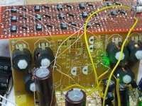
I've been hunched over my soldering for the past couple of days building up an idea I had for improving on PhiDAC SE. I really want to get rid of all the extra caps in that design, but how to get the circuit to be less susceptible to supply noise without them?
My leading hypothesis is that the supply noise is as a result of the classAB output stage of the opamps - I've been curious to see whether if the output stage of an opamp can be disabled or bypassed, whether the supply susceptibility is reduced. The JFET input AD744 has internal pins brought out (thank you Scott Wurcer!) for compensation caps but they can just as easily be used to feed an external classA OPS. So that's what I've implemented on the prototype board in the picture (the red matrix board at the top). Trouble is, the JFETs are a lot noisier than the input stage of the AD8017 so I decided to parallel stages to reduce that - in this case 6 opamps are paralleled - I might try more later. Recycled AD744s are quite affordable on Taobao which is what makes this idea a practical proposition. Initial listening is promising indeed but I want to spend more time with it before making a decision on this. Besides that, my wife needs to approve and the first gash proto using AD744s didn't go down too well.....
The inductors I found a few weeks back turn out not to be available from any Taobao seller at present - they're saying next month but who knows if that's just seller bluster? So for the time being I'll design with the P14s that are shown in the photo, mounted on a daughter board.
Attachments
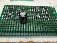
I managed to simplify the IV circuit through discovery of a low-noise bipolar IPS opamp whose OPS was also bypassable - AD829. This chip is even cheaper than AD744 on Taobao and I only need one per channel which saves considerable real-estate on the PCB. Listening is still on-going but sounding quite promising to my ears. The AD744 is still the best choice for the second (active filter) stage as it allows a higher working impedance, meaning smaller (read cheaper) caps.
Attachments
- Home
- Source & Line
- Digital Line Level
- lingDAC - cost effective RBCD multibit DAC design