I have a chifi C3850 clone preamp and LM1875 amp that sound great together. I bought them as stuffed boards from Aliexpress. Total cost was about $150 and together they beat my multi-thousand dollar amp investments from 20 years ago. Specs for these chifi units indicate 110v supply input but mains voltage in my apartment here in Sin City varies from 120 to 125v.
Each unit uses a single linear IC regulator providing fixed output voltage, and both ICs run way too hot to touch. What can I do to keep them from burning up aside from powering the amps permanently through a variac to reduce supply voltage?
Could I swap out the regulators for ones having higher max voltage input and max amps rating as long as the output voltages are the same? None of the other components on either device run hot. I have a tiny heat sink on one of the regulators, it seems to accomplish nothing.
Fit a heatsink to them.
If they are less than 90°C when running, they are probably normal but I would fit a heatsink.
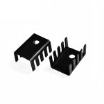
Something like this; https://uk.rs-online.com/web/p/heatsinks/7124314
Calculating voltage drop and using a series resistor to reduce the current, could help but probably not needed.
If they are less than 90°C when running, they are probably normal but I would fit a heatsink.
Something like this; https://uk.rs-online.com/web/p/heatsinks/7124314
Calculating voltage drop and using a series resistor to reduce the current, could help but probably not needed.

Swapping the parts achieves nothing because the dissipation remains the same. It doesn't matter if a part is rated at 1000v and 100amp and 1kW dissipation, if its the same size part it gets just as hot in the same operating conditions as a 30v 1amp 20 watt part. Only a bigger heatsink will reduce temperature in those conditions.
Heat is very subjective. If it is close to actually sizzling a drop of water then it is to hot. If its bearable to touch for 3 or 4 seconds its quite possibly OK.
If you know the input voltage to the regulator, its output voltage and the type of regulator you might be able to fit a low voltage Zener on the input to drop a few volts but that is an unknown without knowing more details.
Posting some pictures would be very helpful. Only a general answer is possible. I believe you are saying that the voltage regulators are getting too hot and you have a tiny heat sink on one that is inadequate. The other has no heat sink?
Running at a lower line voltage is not the way to go. Using a different regulator will not fix the basic problem.
The regulator is dissipating (Vinput - Voutput) X Iout, and it must be able to dump this heat to the air to function properly. The Chifi stuff typically has no, or severely undersized or poorly designed heat sinks. Yes- you must provide an adequate heat sink, that allows air to flow through it to carry the heat away. They should not feel very hot ideally. What heatsink is appropriate will vary significantly depending upon your board geometry and size concerns.
Fit a heatsink to them.
If they are less than 90°C when running, they are probably normal but I would fit a heatsink.
Something like this; https://uk.rs-online.com/web/p/heatsinks/7124314
Calculating voltage drop and using a series resistor to reduce the current, could help but probably not needed.
Personally, I think anything over 75 degrees C is too hot for continuous operation with IC voltage regulators, but I agree, a heat-sink and/or a reduction in applied voltage to reduce dissipation.
[[If its bearable to touch for 3 or 4 seconds its quite possibly OK.]]
both are WAAYY too hot to touch.
[[If you know the input voltage to the regulator, its output voltage and the type of regulator ]]
for the preamp it is an ST L7812CV so I have all the specs. I will research if a zener could help.
[[fit a heatsink]]
very limited space in the width dimension. Maybe I can stack multiple small width heat sinks vertically. I have 50 clip-on sinks for TO-220 arriving soon. Wonder how high I can stack them 🙂
How about making the regulation multi-stage? for example the preamp fixed output is 12v. Could I use two regulators in two stages performing less voltage drop in each stage for final 12v?
Does it sizzle a drop of water. If no then it Is below 100Cboth are WAAYY too hot to touch.
Perhaps a low value resistor might be better than a Zener. You could do with measuring the input voltage to the regs.for the preamp it is an ST L7812CV
Lets play with some numbers...
18 volt in, 12 volt out. Load 250ma. Power dissipation = 1.5watt.
Add a 4.7 ohm. 250ma drops 1.175 volt. Power dissipation now 1.2 watt. Still 4.8 volt headroom.
Add a 6.8 ohm. 250ma drops 1.7 volt. Power dissipation now 1.07 watt. Still 4.3 volt headroom.
Add a 10 ohm. 250ma drops 2.50 volt. Power dissipation now 0.87 watt. Still 3.50 volt headroom.
10 ohm wattage would need to be > 0.625 watt (use a 1 watt)
Second picture looks to have room for a small heatsink and there is lots of space to the left or in front of the caps. Room for a resistor or move reg and add a bigger heatsink.
First picture is tight on room but I think something a bit better than that heatsink would fit. Also reduce voltage to that reg. Every little helps, even a couple of volt reduction.
[[measuring the input voltage]]
Oh yes i wanted to but fear to create a short in such limited spaces. Maybe i will try from the reverse side of the boards
[[sizzling water]]
I bet it will,sure sizzles my finger. Don't believe they will last as is...
Resistor at inputs seems easy to try...
Oh yes i wanted to but fear to create a short in such limited spaces. Maybe i will try from the reverse side of the boards
[[sizzling water]]
I bet it will,sure sizzles my finger. Don't believe they will last as is...
Resistor at inputs seems easy to try...
If you try a resistor then make sure you keep a cap at the input of the reg to decouple the pin and keep the reg stable. It only needs to be a small value like 4.7uF
You’d be surprised to see how far a very small metal tab heat sink goes in situations like this. The only real issue is it flopping around putting stress on the leads or shorting risk, but all that can be mitigated. I’d use an inch long piece of angle aluminum, glued to the board on one edge between the trace and the row of BVY27’s. Leave a little gap at the base on the regulator side (requires a bit of hacksaw or Dremel work). Sand and polish with 400 grit, spray paint it black except for under the TO-220 and it will look like it’s supposed to be there.
Dropping input voltage is a band-aid, and a poor one at best, trying to make up for a serious design mistake. Thermal considerations are often forgotten in an effort to cram too much electronics into a little box. Neither regulator looks like it was given proper space from surrounding components to even fit a proper heatsink. If you can't fix the thermal issue with the size you have to work with, here is what you really need to do- remove the regulators, and connect them to the PCB with flexible wires several inches long soldered to the legs of the regulators, so you can screw the regulators to an adequate heatsink. The only proper solution here.
The solution is to use a heatsink that is big enough to reduce the operating temperature. Semiconductors under continuous heat stress have a short lifetime. As mentioned above, you can solve your problem by using a sufficiently large heatsink. Remove the regulators from the PCB where they don't have enough space and connect them preferably using ribbon wires. You can reuse ribbon cables such as IDE cables.
Design oversights like this are what’s typically wrong with Chi-Fi products. Two watts of dissipation will run a TO-220 to Tj(max) in free air. With this logic a watt and a half, one and 3/4 is “fine”, but in practice, too hot. Even a small heat sink will help with that A LOT.
You see this in older 1970’s receivers too - with the PCB turned to carbon. With todays stupid lead free solders, it will go bad long before that happens.
You see this in older 1970’s receivers too - with the PCB turned to carbon. With todays stupid lead free solders, it will go bad long before that happens.
I once worked on an Ampeg Bass amplifier where the Regulator had got hot enough to melt the solder joint.
I also have an Ecler Mixer powersupply (FA50) which was getting very warm in use, and invaribly is the first part of the mixer system to die.
In both cases add on heatsinking has saved the units.
Dropping the input voltage to the regulator may help, but only because it spreads the energy dissipation to additional components!
Definitely move the regulator off board by extending its leads so you can get it somewhere with the room for a heat sink. Make sure the tab of the regulator is isolated from the chassis as it may not be isolated within the regulator. Somewhere where air can move is best! Use solid wire of at least 18 gauge and shrink tube the leads but leave them full length as they also dissipate power. You can even add small film caps across the leads on input to ground and output to ground. Use the largest heat sink that will fit in the chassis without shorting on the case. It’s a lot of work but if you want the thing to last it’s worth it.
Had not thought of pulling the regulators off the board to make room for proper heat sinks but that is a very interesting idea. I like the sound of this combination of preamp/poweramp too much to allow them to burn up so I will limit use of them until I can implement something that seems safe...
Thanks to EVERYONE who chimed in with ideas! I learned a lot!
Thanks to EVERYONE who chimed in with ideas! I learned a lot!
- Home
- Amplifiers
- Solid State
- Linear IC Voltage regulators too hot to touch on both amp and preamp