perhaps the regulator input voltags relative to the output is too high. try a lower voltage AC wallwart that is your case.
I would use a chassis mounted heat sink, and 1.5 square mm wires to PCB, observing insulation precautions.
And if it is a wall wart, then change to one with a lower output voltage.
If it is inside the unit, a 10 Ohm 10 Watt series resistor on mains side will reduce the input volts to transformer, that is a common problem nowadays with higher mains volts.
Whacked out alternate is a wideband (90-270V) laptop power supply....that works very well, put some small caps in parallel to reduce noise...4.7 /47 / 470 uF 50 or 63V, between + & - rails.
That takes care of higher mains volts, and many people have a spare supply for an old laptop, which is not in use.
Its is often the same problem with the chinese boards....there is no heatsink or it is to small. The heatsink is not isolated to the component, never using thermal paste...
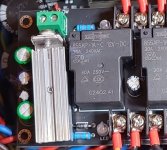
The LM 7812 on this speaker protection was to hot, because the heatsink was too small. Too small for a difference of 4 volts and few mA.
I had low space to the top plate of the case, i had to choose this way....now everything is fine...
The LM 7812 on this speaker protection was to hot, because the heatsink was too small. Too small for a difference of 4 volts and few mA.
I had low space to the top plate of the case, i had to choose this way....now everything is fine...
Attachments
Most of what has been said already but I would add some 5 or 6 mm ventilation holes near the new TO220 heatsink (carefully check not to damage PCB tracks) and bend the electrolytic caps away from the hot regulator. Maybe the caps already have had enough heat to make them so so. Improving air flow with added holes does work in practice.
* If you check the recent versions of that preamp you will notice they solved it. Apparently it does not become extremely hot.
** Of course we should know what the input voltage and the current draw are for 100% fitting advice.
*** It does not hurt to check electrolytic cap brands and types just to know if stuff is well built or not.
Last edited:
A linear regulator almost has to have a heatsink. If I remember right a TO-220 theta J-air with no heatsink is around 40 degrees C/W. Most linears want a minimum of 2V drop. So just 1/2A draw thru it is 1W using the minimum input voltage, which you really can't. You have to have some slop for line voltage variation and high loads causing droop on the input voltage caps. So for a 12V regulator you want 15-16V typical in. And you have to do the thermal design for worst case, so maybe even 17V if the AC line is high. 16V gives a 4V drop and at 1/2A draw that is 2W the regulator is dissipating. So 2x40W/C is 80C temp rise and if ambient is 25, which is very optimistic in an enclosure, you're over 100C. About the only time I don't heatsink a regulator is if I know we are talking 100ma or less draw.
If there is a voltage difference, then use mica insulators with thermal grease.The heatsink tab of the 78xx regulator should be ground (some are not!) so make sure there is no voltage difference between the tabs and the other heatsinks or chassis areas you may mount them to.
Even if there is no voltage difference and both are 'ground' you could still unintentionally introduce a ground loop bolting them to the case.
Given it all works OK I would just shave a little off the input voltage as I outlined at the start. You could also ground the lift the centre pin of the reg with a 1N4148 to increase the 12v to 12.6 which I'm sure would not cause any operational issues and it would have the effect of reducing the input/output differential that little bit more. Every little helps and it should be possible to make a big difference by simple means.
Given it all works OK I would just shave a little off the input voltage as I outlined at the start. You could also ground the lift the centre pin of the reg with a 1N4148 to increase the 12v to 12.6 which I'm sure would not cause any operational issues and it would have the effect of reducing the input/output differential that little bit more. Every little helps and it should be possible to make a big difference by simple means.
To wrap up this thread, (thanks again for all suggestions!) I ended up "keeping it simple" and going with mechanical fix attempt. Bought a bag of these aluminum clip-on heat sinks from the bay, and they are soft enough I could bend the fins to fit. I should probably add some heat conducting grease where the two sinks mate.
Now I can hold my finger to the fins for 10 seconds at least before it becomes too uncomfortable and I have been running the amp pretty much 10 hrs per day with no problems. Sounding great fed with a class A Centrance USB dac/preamp.
Maybe my next purchase will be an infrared temperature camera from Ali - if and when the tariffs go away.

Alright, but the aluminium should be at the back (where the silicon die is) of the IC. 10sec test is a good observation, now leave it as it is.
With unmachined mating surfaces, and only one mounting bolt, his arrangement is about as good as he can do
with that package, at least after he adds the thermal grease.
with that package, at least after he adds the thermal grease.
I would have done it little differently. A 'T' like piece of SMPS heatsink or thick aluminium & some thermal grease. But he did it well.
Last edited:
I keep old motherboards around for their small heat sinks.
High temperature silicon sealant, as used in cars, is a decent adhesive + heat conductor, if the layer is not too thick.
Alternate would be chassis mount, wires to PCB, then plenty of room for a really big heat sink.
High temperature silicon sealant, as used in cars, is a decent adhesive + heat conductor, if the layer is not too thick.
Alternate would be chassis mount, wires to PCB, then plenty of room for a really big heat sink.
A larger heatsink touching the back of the regulator (with some heat conducting grease) would be better and more reliable as it is bolted. It is all about enlargening the surface. I don't like the thought of a clip on heatsink coming off in energized state.
If that aluminium surface right on the picture is the upper cover it sure needs some ventilation slots/holes as the heat should be given to the environment and not stay in a closed casing. This together with ventilations slots/holes in the bottom for fresh air. It is quite simple really. If we would know actual numbers it would not surprise that the dissipated power is not much at all. The heat just stays where it should not be.
To improve reliability it is a good thing to use flat washers with M3 hardware. Not serrated ones.
Last edited:
I also back the idea of mounting the regulator on the chasis, with small decoupling capacitors of course. The best possible solution.
I miss Cs between the legs of the regulators like in datasheet?!
it reduces oscillation and heats up less? And sounds better
it reduces oscillation and heats up less? And sounds better
There are many caps around the regulator. Likely caps that don't freeze 🙂
The 7812 seems to be used for a loudspeaker protection circuit and/or relays. Anyway the main cause is a too small heatsink in the amplifier and no heatsink at all in the C3850 clone (an error that has been corrected in recent versions). Requires just 2 normal sized U shaped TO220 heatsinks and 2 very tiny dots of thermal grease to solve adequately by a layman.
The 7812 seems to be used for a loudspeaker protection circuit and/or relays. Anyway the main cause is a too small heatsink in the amplifier and no heatsink at all in the C3850 clone (an error that has been corrected in recent versions). Requires just 2 normal sized U shaped TO220 heatsinks and 2 very tiny dots of thermal grease to solve adequately by a layman.
Last edited:
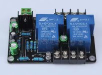
The solution to that is not to run the GD relay through the regulator. The coil doesn’t need regulated voltage. Got at +/-55V supply? Use a 48 volt coil and a dropping resistor. Run the control ICs off the regulator.
- Home
- Amplifiers
- Solid State
- Linear IC Voltage regulators too hot to touch on both amp and preamp