I've been looking at various preamp line stages for a while before I start to build a prototype on the bench. I'm looking for a gain of about 6 x to boost the typical 500mV most of my sources kick out, IE PC etc to around 1.5v + some headroom.
Most commercial approaches I've looked at so far use one half of an ECC83/12AX7 in a standard common cathode voltage gain stage with the other half used as a cathode follower for low OP Z. First question, AFAIK, the ECC83 makes a crap CF, why?
A few designs use the SSRP, a circuit topology I'm unfamiliar with. As far as I can see, the SSRP is essentially a cascode, with a resistor between the bottom triodes anode and top triodes cathode, which develops an OP voltage. Second question - as the SSRP has a higher OP Z than a cathode follower, why use it? Does it have any other advantages I'm missing?
I'm quite tempted to use a Russian 6N2P-EV as a high gain IP stage with local FB followed by a ECC88 or 6CG7 CF unless the SSRP or any other topology is a better option.
Any thoughts/ideas/FB welcome, Andy.
And if that design is still too much gain, you could try a 6V6 triode strapped, with or without a CF.
6V6 line preamp
jeff
6V6 line preamp
jeff
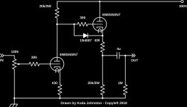
Thanks Koda... CCDA? An acronym I've not come across. Nice simple circuit. BTW, like your tangential approach to amp building.
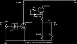
From a quick felt tip pen load line on a screenshot of 6CG7 (6SN7 in B9J )mutual characteristics graph, gain is approx 20. IP stage not de-coupled so THD low, gain low-er, biased at about -6v. OP Z of CF roughly >1k.
I'll knock it up on the bench tomorrow, Andy.
Edit, posted at same time as Jeff's post.... I did think about using a pentode as I have a good stash of NOS 6AU6's which I've used with a CCS anode load, triode strapped in an amp. Something to bear in mind, thanks.
Last edited:
It's SRPP (shunt regulated push pull). It is push pull in operation; but the operation of the circuit is very load specific. It has to be optimized for the load that is connected to it. Not very ideal for a "universal" preamp.
SRPP? I see a gain stage and a direct coupled cathode follower.
He meant the proper acronym is SRPP, not SSRP.
"It's SRPP (shunt regulated push pull). It is push pull in operation; but the operation of the circuit is very load specific" there seems to be some confusion, it's definately SRPP like this circuit here - DIY ECC802S (12AU7 / ECC82) Vacuum Tube SRPP Preamplifier Are you saying all SRPP circuits are dependant on load John?
Merlin Blencowe published an excellent article on the history, operation and design considerations of the SRPP circuit " The Optimized SRPP Amp" in the May and June 2010 issues of AudioXpress. In this article he explains when an SRPP circuit is and is not a true SRPP and why it is dependent on its load. If you can access this article it's well worth the read.
Thanks Koda... CCDA? An acronym I've not come across. Nice simple circuit. BTW, like your tangential approach to amp building.
From a quick felt tip pen load line on a screenshot of 6CG7 (6SN7 in B9J )mutual characteristics graph, gain is approx 20. IP stage not de-coupled so THD low, gain low-er, biased at about -6v. OP Z of CF roughly >1k.
I'll knock it up on the bench tomorrow, Andy.
Edit, posted at same time as Jeff's post.... I did think about using a pentode as I have a good stash of NOS 6AU6's which I've used with a CCS anode load, triode strapped in an amp. Something to bear in mind, thanks.
CCDA == Constant Current Draw Amplifier. I found on the idea Tubecad years ago.
Here's the original article: CCDA: constant-current-draw amplifier
And thanks. I like to think outside of the box 🙂
Koda
As You don't look for more then 6x i suggest you use a E88CC in the configI've been looking at various preamp line stages for a while before I start to build a prototype on the bench. I'm looking for a gain of about 6 x to boost the typical 500mV most of my sources kick out, IE PC etc to around 1.5v + some headroom.
Most commercial approaches I've looked at so far use one half of an ECC83/12AX7 in a standard common cathode voltage gain stage with the other half used as a cathode follower for low OP Z. First question, AFAIK, the ECC83 makes a crap CF, why?
A few designs use the SSRP, a circuit topology I'm unfamiliar with. As far as I can see, the SSRP is essentially a cascode, with a resistor between the bottom triodes anode and top triodes cathode, which develops an OP voltage. Second question - as the SSRP has a higher OP Z than a cathode follower, why use it? Does it have any other advantages I'm missing?
I'm quite tempted to use a Russian 6N2P-EV as a high gain IP stage with local FB followed by a ECC88 or 6CG7 CF unless the SSRP or any other topology is a better option.
Any thoughts/ideas/FB welcome, Andy.
you already are contemplating. A cathode follower using E88CC will be very
low impedance and the amp would be insensitive for loading.
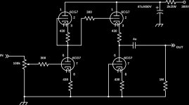
I've used the same circuit but with cascode MOSFET current sources in place of the load resistors for the 6SN7, 300V B+ and 2 red LEDs in series with the cathode to bias the voltage gain stage. Works well and the CCSs simplify the biasing.
I've used the same circuit but with cascode MOSFET current sources in place of the load resistors for the 6SN7, 300V B+ and 2 red LEDs in series with the cathode to bias the voltage gain stage. Works well and the CCSs simplify the biasing.
I do the same but using triodes instead of MOSFETs. In the example I posted, you'd replace the 20k resistor with another 6CG7 like in this example. It uses twice the number of tubes, but moves most of the waste heat above the chassis allowing for a small, hole-less enclosure.
Attachments
Last edited:
I do the same but using triodes instead of MOSFETs. In the example I posted, you'd replace the 20k resistor with another 6CG7 like in this example. It uses twice the number of tubes, but moves most of the waste heat above the chassis allowing for a small, hole-less enclosure.
Nice, simple. Not exactly Aikido, but topologically real close. I've always kind of wondered what the gain of the left-triode-stack is, as a function of mu, say.
One of the things that I've also mused upon is that insofar as biasing goes, the lower, left triode looks ripe to have a 2-red-LED-in-series cathode bias instead of the 430 Ω resistor. The upper triode could be similarly endowed (for symmetry-of-diagram), but also one could just determine a suitable 'naked resistor' like the 430 Ω job, too.
Might even be 430 Ω.
Indeed … with as-shown 6CG7 (https://frank.pocnet.net/sheets/127/6/6CG7.pdf), it looks like a 3.5 V cathode LED bias would deliver about 10 mA at 150 V plate-to-cathode potential. E=IR, R = E/I = 3.5 ÷ 0.010 = 350 Ω. Or 470. Or whatever close. You seriously could probably use any resistor in the range of 270 to 680, and everything would work just fine.
But… the one thing that an LED-on-cathode bias scheme does is that it holds the cathode 'hard' at the 2⋅VF conduction level, regardless of signal excursions. A 'naked resistor' is substantially different, inducing an in-phase signal onto cathode, as a kind of negative feedback. Lower gain, of course. Higher linearity, of course. Probably more desired for a preamp, of course. Except if one needs a light show … of course.
Anyway, as I said.
Musing upon.
GoatGuy ✓
Yes, you're right. This is Aikido without the mojo. I'll call it Active CCDA. I don't need the effects of it since I use clean power in the first place by SMPS or brute force. You'll remember I commonly use a 3300uF cap in the final position of my power amplifiers, and a phono preamp will be 500uF or so.
From what I understand, the gain is 1/2*mu of the first tube. In this example, a gain of 10 with a bypassed cathode, probably about 8 without.
One day I'll eff with LEDs, but I'm more likely to use a battery inline with the grid. 😀
You are correct though, the unbypassed resistors reduce distortion at the cost of gain and higher Zout.
The nice thing about using a battery like this is it will never go dead (if it's carbon or another composition with a long shelf life) because there is no current drawn, it's a simple voltage source.
Attachments
Last edited:
From what I understand, the gain is 1/2*mu of the first tube.
Yes, the gain of the first stage (if unloaded as here) is exactly mu/2,
assuming that the tube sections match and the cathode resistors are equal.
A triode current source AC impedance, while better than a plain resistor, can't touch the 40M to 60M that a cascode MOSFET can achieve in the audio band. As to heat, the heat sink can be mounted on top of the chassis.
Yes, but couldn't you use pentodes to achieve the same result? Seems like a good use for those 6GH8A tubes we have lying around from the "color killer" circuits of old TVs 🙂 If you use depletion mode MOSFET or JFET they should drop in without much change other than the cathode resistor?
As for heat sinks on top, but then people would know you used sand? LMAO
Last edited:
Yes, the gain of the first stage (if unloaded as here) is exactly mu/2,
assuming that the tube sections match and the cathode resistors are equal.
I thought so. Does that mean it's 1/2*mu unbypassed, and higher if it is?
- Home
- Amplifiers
- Tubes / Valves
- Line preamp questions.