Was going to beg for acoustic absorption data on felt but decided to look for it myself and found a source of detailed acoustic absorption test results with enough panel construction data so panels can be DIYed
Acoustical Tests | Test Results | Resources | FabriTRAK(R)
The first report at the link shows results for .5" of felt, others show results for various thicknesses of rigid fiberglass
Acoustical Tests | Test Results | Resources | FabriTRAK(R)
The first report at the link shows results for .5" of felt, others show results for various thicknesses of rigid fiberglass
Mark, I don't think you got what I was saying, let's see it in graphs:
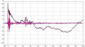
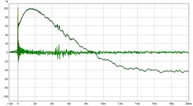
IR result with global EQ to get the magnitude flat:

Now let's run that trough DRC-FIR:

FIR allows change over time, not the same bump at a certain frequency that always stays the same over time. This is set to minimum phase though, within the DSP solution, computing wise. These two IR's sound quite different, even if the magnitude would be set the same.
You are not correcting a single crossover-less driver here, you have a whole bunch of them. They arrive at slightly different intervals at the listening spot/area.
See how the reflection at 4.5 ms is still there though? But the impulse has been turned back to it's original shape, instead of the diffuse top end of the IIR EQ magnitude correction by itself. This isn't room correction. It is correction of the drivers to act as one.
Not unlike a multi way, this correction isn't a fix for every position, but not fixing it isn't a valuable solution either. I do choose a distance and averaging multiple measurements can make it optimal over an area. Move up/down or left/right and you still get the benefits. Move far enough away (not a valid option in my listening space) and things might not be as optimal anymore, but it would still be way better than not adjusting it at all.
IR result with global EQ to get the magnitude flat:
Now let's run that trough DRC-FIR:
FIR allows change over time, not the same bump at a certain frequency that always stays the same over time. This is set to minimum phase though, within the DSP solution, computing wise. These two IR's sound quite different, even if the magnitude would be set the same.
You are not correcting a single crossover-less driver here, you have a whole bunch of them. They arrive at slightly different intervals at the listening spot/area.
See how the reflection at 4.5 ms is still there though? But the impulse has been turned back to it's original shape, instead of the diffuse top end of the IIR EQ magnitude correction by itself. This isn't room correction. It is correction of the drivers to act as one.
Not unlike a multi way, this correction isn't a fix for every position, but not fixing it isn't a valuable solution either. I do choose a distance and averaging multiple measurements can make it optimal over an area. Move up/down or left/right and you still get the benefits. Move far enough away (not a valid option in my listening space) and things might not be as optimal anymore, but it would still be way better than not adjusting it at all.
Attachments
Last edited:
You are not correcting a single crossover-less driver here, you have a whole bunch of them. They arrive at slightly different intervals at the listening spot/area.
See how the reflection at 4.5 ms is still there though? But the impulse has been turned back to it's original shape, instead of the diffuse top end of the IIR EQ magnitude correction by itself. This isn't room correction. It is correction of the drivers to act as one.
Not unlike a multi way, this correction isn't a fix for every position, but not fixing it isn't a valuable solution either. I do choose a distance and averaging multiple measurements can make it optimal over an area. Move up/down or left/right and you still get the benefits. Move far enough away (not a valid option in my listening space) and things might not be as optimal anymore, but it would still be way better than not adjusting it at all.
Thanks Ron, very nice explanation. I do understand, have understood, all that.
I guess I'm uncertain how you can say once FIR is applied, that it's not room correction, that the correction is getting the drivers to act as one.
How can it not be both? And how can you separate one from the other?
What does seem more certain to me, is the excellent job you have done with the speaker and room tuning room, given how it holds together with up/down or left/right movement.
I would expect distance to speaker to be considerably more problematic, as you say. Heck, even with the comparatively simple multi-ways, I can only nail timing to a single given distance.
Well, that's where the frequency dependent window comes in.
I can give a couple of examples at certain frequencies (as I'm going over a new for me experiment right now):
The correction window at 20000 Hz is 0.58 ms long (chosen by me based on a desired listening distance and the separate arrivals of the drivers in the array).
The correction window at ~5000 Hz is 1.22 ms long.
While frequency drops, I'm using ever shorter window lengths, about 4 to 5 cycles worth at mid and bass frequencies.
For this above example to work, we need to get the reflections out of the equation first.
Either trough room treatment (my favorite) or trough the averaging of multiple measurements.
While keeping the correction window short, you're in and out before the reflections or remainders there-off arrive at our microphone. If the room treatment is effective, you'll immediately see that in the IR's.
The above plots are a new experiment for me, I've taken a foam ball, with a microphone flush at the side and positioned that at the sweet spot. In other words, where my left ear would be when sitting equal distance to the loudspeakers. Still need to do the same for the right speaker.
The foam ball gives me an idea of what (actual) head shading does to the cross talk at my listening position.
For damping panels (I only have 3, quite large ones) I looked at the RT60 data to see where I had excess energy, while also placing them at the first reflection points. The thickness was determined by looking at the RT60 plots, determining to what lower frequency i could or should absorb to keep the balance of the FR curve similar for the main wave front and the later arriving energy.
That's a mouth full, below schroeder frequency, I cannot separate the room from the array itself anymore. That's why a bit of hand labor will be needed to ensure a good balance throughout the room at these frequencies. That is basically getting lots more measurements over a wider area and see the commonalities. So some tweaks are done to get the bottom end right.
Lots of listening is done to ensure I'm moving in the right direction. I've done it several times so I learned a lot of the room/array combo and learned what I can and cannot fix.
My final purpose is getting the best sweetspot I can get while retaining a very good overal balance throughout the room. I don't want a single "head in vise" listening sweetspot and aim for a good balance. The room treatment goes a long way in achieving that. Without it, it gets way more unpredictable. While that can still be fun, I do aim for more.
This setup doubles for home theater (without an actual center channel) and has to work for my whole family to enjoy.
So far I've already achieved that, but I'm always looking for more to squeeze out. Hence the continuous stream of experiments to learn more.
Number one on my list of improvements for straight arrays:
- Adding damping panels (this greatly improved overal achievable tonality in the room)
Other projects worthy of mentioning:
- Custom DSP processing done by FIR vs the former EQ only (Yes I've used that too). Biggest improvement of all.
- Adding ambient channels with my own mix of content (highly recommended)
- Mid/Side EQ to combat cross talk (currently trying to get even more out of that)
I've done lots more experiments, not all were equally successful. Still have to try:
- Adding a pair of single subs, not to take over but to augment the arrays (creating headroom and improve left/right balance)
- Playing with (delayed) ambient tweeters behind main speakers?
And anything else I can come up with...
Last edited:
Well, that's where the frequency dependent window comes in.
I can give a couple of examples at certain frequencies (as I'm going over a new for me experiment right now):
The correction window at 20000 Hz is 0.58 ms long (chosen by me based on a desired listening distance and the separate arrivals of the drivers in the array).
The correction window at ~5000 Hz is 1.22 ms long.
While frequency drops, I'm using ever shorter window lengths, about 4 to 5 cycles worth at mid and bass frequencies.
For this above example to work, we need to get the reflections out of the equation first.
Either trough room treatment (my favorite) or trough the averaging of multiple measurements.
While keeping the correction window short, you're in and out before the reflections or remainders there-off arrive at our microphone. If the room treatment is effective, you'll immediately see that in the IR's.
Looking at your correction window at 20,000Hz of 0.58ms, that appears to be very close to the time-of-flight difference at 2.7m, between the center and ends of the array.
Correct? Is that how you chose it ?
So you use about 6 cycles at 5kHz, and let it taper down eventually to 4 cycles?
If all that is correct, that appears to be some fairly aggressive smoothing...which makes good sense to me.
I get the idea of gating is to try to stop the measurement prior to receiving reflections. I've always felt this is the best we can do if we can't measure outdoors.
The arrays' inter-dependency with the room is of course making me rethink gating's value...a process you're probably watching with amusement Lol
I just gotta keep thinking about this....still juggling thoughts here..
One area we always fully agree on is the value of working on room acoustics.
The last room I tuned extensively followed the same pattern you described...placed absorption based on the RT60 curve above Schroeder, first on early reflection points, then dispersed through the room. Took alot of material for a 330 m^3 room. It's a bitch to put rugs on a 12 ft ceiling !! Also used a live-end dead-end approach, with the dead-end behind the speakers.
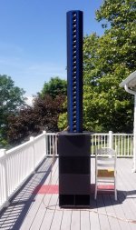
Today, for grins I put a straight array on top of one of my subs out on the deck. Crossed them at 100Hz with a linear phase LR72, because that's the low-pass in place on the sub.
I used the same indoor FIR file built off the average indoor measurement last posted, albeit with the HPF added.
Sounded pretty dang good for a quick throw together 😀
What was fun was trying some simple steering... I curved the top of the array to an 18ft listening distance radius, and the sound which was at ear height shifted to middle as expected. Then I amplitude shaded the bottom up, starting with -2.5dB to 0 shading at the top. Sound image climbed to the top section nicely....way up there!
Attachments
True, it is based on arrival times, but only after spending a lot of time changing the window shape/time manually and just listen to it, even exaggerating the settings to find its limits, to know/learn what that sounds like. The goal was to find the shortest window I could get away with while still having excellent (sonic) results.
I found that a longer window on the top end made for an improved perception of detail, focus and imaging, while a long window at midrange frequencies could result in unnatural sounds, and also be very position dependent for the listener.
I've tried many many combinations to get a feel for this, this kind of processing had to work on different listening material to make me accept it.
While I do think we sure have a mixed bag of quality in recordings, I won't accept that all recording engineers are deaf.
Most older material is actually of quite good quality. When studio's where still the common way to record 😉.
Not to change into a discussion of quality of recordings, I've spend about half a year just trying stuff, before arriving at my personal preferred template.
A similar amount of time was spent to find a house curve that worked for me. That actually started working on a wider range in my song library after introducing the mid/side EQ I've mentioned before.
I hope I speak for more than one person if I say it's no fun to build speakers and be able to enjoy only a couple of "chosen" recordings. I'm in this game to be able to listen to what I call the soundtrack of my life!
As I've probably mentioned before, one program's frequency dependent window isn't the same as the same settings in other programs. I've done some comparisons of REW and DRC-FIR to verify the differences between these two. Here's a sample:
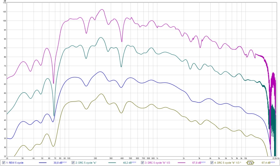
The dark blue trace is a 5 cycle REW window, being compared to 2 different ways of achieving a same length 5 cycle window within DRC-FIR, and adding one filtered DRC trace to get comparable results to what REW shows
Throwing a 1/6 oct smoothing on top of DRC's 5 cycle "b" trace was the closest to a standard 5 cycle window in REW.
It's easy to see the larger amount of detail in both the DRC "b" and "s" curves, the "b" curve being more edgy, so that's why I use the "s" style of filtering. The differences between these "b" and "s" methods explains why one looks a little edgy:
I found that a longer window on the top end made for an improved perception of detail, focus and imaging, while a long window at midrange frequencies could result in unnatural sounds, and also be very position dependent for the listener.
I've tried many many combinations to get a feel for this, this kind of processing had to work on different listening material to make me accept it.
While I do think we sure have a mixed bag of quality in recordings, I won't accept that all recording engineers are deaf.
Most older material is actually of quite good quality. When studio's where still the common way to record 😉.
Not to change into a discussion of quality of recordings, I've spend about half a year just trying stuff, before arriving at my personal preferred template.
A similar amount of time was spent to find a house curve that worked for me. That actually started working on a wider range in my song library after introducing the mid/side EQ I've mentioned before.
I hope I speak for more than one person if I say it's no fun to build speakers and be able to enjoy only a couple of "chosen" recordings. I'm in this game to be able to listen to what I call the soundtrack of my life!
As I've probably mentioned before, one program's frequency dependent window isn't the same as the same settings in other programs. I've done some comparisons of REW and DRC-FIR to verify the differences between these two. Here's a sample:
The dark blue trace is a 5 cycle REW window, being compared to 2 different ways of achieving a same length 5 cycle window within DRC-FIR, and adding one filtered DRC trace to get comparable results to what REW shows
Throwing a 1/6 oct smoothing on top of DRC's 5 cycle "b" trace was the closest to a standard 5 cycle window in REW.
It's easy to see the larger amount of detail in both the DRC "b" and "s" curves, the "b" curve being more edgy, so that's why I use the "s" style of filtering. The differences between these "b" and "s" methods explains why one looks a little edgy:
MPPrefilterType said:This parameter can be either B for the usual band windowing prefiltering stage or S for the sliding lowpass method. The first method splits the input response into log spaced bands and window them depending on some parameters but basically with a window length which decrease exponentially with the center frequency of the band. The sliding lowpass method instead filters the impulse response with a time varying lowpass filter with a cutoff frequency which decreases exponentially with the sample position with respect to the time axis zero. This last one is a stepless procedure.
Using either a lowercase b or s for the MPPrefilterType parameters enable the single side version of the prefiltering procedures. The procedure is applied starting from the impulse center, leaving the first half of the impulse response unchanged. This gives less pre-echo artifacts, and should be used when the pre-echo truncation inversion procedure is used. Please remember to set the prefiltering parameters to values which are adequate for the procedure used.
Was able to get some decent quality import birch ply today in large enough sheets to work.
with. Hopefully will have time next week to get started. CNC template comes today. I'm going to try and bend 3/4" ply with kerf lines but grabbed some 1/2" too in case that is too difficult.
with. Hopefully will have time next week to get started. CNC template comes today. I'm going to try and bend 3/4" ply with kerf lines but grabbed some 1/2" too in case that is too difficult.
Made some test pieces, one with recess for driver flange recessed just enough to be flush, the other routed from backside for rear driver mounting putting surround flush with front face.
I think I'm going to try the second way. Better for diffraction and looks a little better. My biggest concern is it leaves only about 0.3" material thickness and that when I try to bend the face it will only bend at driver midlines. I placed all drivers as closely as possible so material is pretty sparse in-between. I may have to cut kerf lines across backside of face pretty closely spaced that go to that .3" depth to help the bend uniformity, maybe fill with glue while bent to restore some strength.
Only way to know is make one and see how it goes.
Definitely will need braces but looks like you left just enough room between the woofers. Then some fine sculpting to fit between the pair of tweeters on the same line...
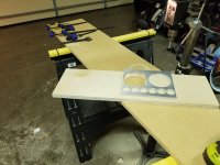
Snapshot of the test piece and template to give some idea of material that will be left. Not much! I will try to find some way to brace/stiffen the panel but not a lot of room to work with.
Nice progress! And gotta love that router template.
I'm watching very curiously how you end up fitting the larger driver to the curvature
Definitely will need braces but looks like you left just enough room between the woofers. Then some fine sculpting to fit between the pair of tweeters on the same line...
The recessed profiles for driver flanges will touch or nearly touch. I can still fit a horizontal stiffener but would have to be installed after drivers. I think I'll just have to get to that point, see what it looks llike installed and go from there.
Nice progress! And gotta love that router template.
I'm watching very curiously how you end up fitting the larger driver to the curvature
I curious about that too! Mounting from the backside will help some with that as it will help visually hide any gap. Just have to make sure I get a good seal and that installing drivers doesn't try to locally flatten the face too much.
just need a thick enough gasket of an appropriate durometer. Its about 1/64" for a tweeter so for a woofer you'll need something that will conform between 1/16" and 1/8". and don't tighten the mounting screws too tight. In fact, I would isolate their heads with a rubber washer and just tighten them enough to compress the washer a bit.
Argh. Set screw on collar of new template bit was loose letting top bearing ride up and gouge the aluminum template. Now ive got to patch it with some marine epoxy before I can get back to making sawdust. 🙁
Argh. Set screw on collar of new template bit was loose letting top bearing ride up and gouge the aluminum template. Now ive got to patch it with some marine epoxy before I can get back to making sawdust. 🙁
Ouch, ....well glad at least you can fix it.
I hate when I screw up a template...like when I get overconfident I can withdraw the router before it quits spinning 😱
Fixed the router template. While I was waiting for resin to harden I made a template for cabinet sides. I could have just made the first side and used it as template for the others, but if I like these I'll make more for additional channels and wouldn't want my template to be part of an assembled cabinet!
- Home
- Loudspeakers
- Full Range
- Line array steering ?