I don't agree with the corner is the worst place ever richie00boy...
In theory, it should be the best place since you excite only three room modes, ceiling and two walls.
Near the center, you excite 5 room modes, ceiling and five walls...
You lose also 6 dB of headroom, that's huge.
In theory, it should be the best place since you excite only three room modes, ceiling and two walls.
Near the center, you excite 5 room modes, ceiling and five walls...
You lose also 6 dB of headroom, that's huge.
Actually, the corner placement excites all room modes. However, a good argument can be made that maximally exciting all available modes can give more even response than other placement locations on walls or out in the room that only excite a couple of modes.
What looks smoother... a bunch of overlapping peaks closer together or a few scattered ones spaced further apart? 😉
Of course, the real answer is that each room is different, and both listening and measurements should be used to make the proper location determination. I find it short sighted however to rule out corner placement out of hand because of poorly-formed logic.
I'm not ruling out corner placement, was just pointing out the room mode issue. It could end up being OK there. As you point out all rooms are different 🙂
simon5 said:This is a subwoofer I made, when placed in a corner, using RatShack Meter with correction factors...
is the mic at the listening position? You used EQ?
No EQ, listening position, small room so close to the subwoofer.
Probably lucky hehe!
This graph is not done with 1 Hz increments so there's probably room modes hiding in there I guess. I'll try to do a better graph next time.
Probably lucky hehe!
This graph is not done with 1 Hz increments so there's probably room modes hiding in there I guess. I'll try to do a better graph next time.
Hess,
If you have to use a corner, then an array is better because the ceiling to floor mode will be minimized. The problem I see with the idea is that you can't run cheap subwoofer drivers unfiltered no matter what their size. Smaller drivers could work but you'd need EQ and or filtering to achieve decent extension and flatten the response, however, if you found just the right small driver you might be able to achieve exactly what you want with the corner loading giving you the extra extension that the small drivers couldn't achieve on their own. I have no idea how you'd go about identifying what that ideal driver would be.
A corner horn array could give you the extension you want using small drivers and use acoustical filtering to limit the top end, but the design and build would be a lot more difficult.
With SQ being the main requirement and that you want to use an array with cheap drivers I'd say go dipole, but I have no idea what corner placement would do to a dipole sub.
corner Sub
Hi,
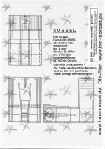
may I show your my SUBSEL free download
hornsub, place it directly in the corner lay it on a side
don´t use it as an armchair.
More or less easy to build only two angles,
I prefer the version with two 6,5" driver
for example Dayton
Hi,
may I show your my SUBSEL free download
hornsub, place it directly in the corner lay it on a side
don´t use it as an armchair.
More or less easy to build only two angles,
I prefer the version with two 6,5" driver
for example Dayton
Attachments
hm,
great horn designs. Your book is nice. Unfortunately, this cabinet is to large for my space constraints. Thanks anyway. Maybe one day I will be able to hear one of your horn speakers.
Hezz
great horn designs. Your book is nice. Unfortunately, this cabinet is to large for my space constraints. Thanks anyway. Maybe one day I will be able to hear one of your horn speakers.
Hezz
JohninCR,
Thanks for the input. Your idea sounds very interesting. The input to the sub is already active low pass filtered with the A/V receiver. I would hope that the crossover is implimented in the digital domain. In either regard there should be little information over 120 Hz so low pass filtering smaller drivers doesn't seem necessary. But I do not know enough about line array theory to comment with much intelligence.
But Dayton makes some good but not high end 8 inch drivers for 22 USD each. What about having two rows of closly spaced 8 inch drivers from floor to ceiling.
Hezz
2 columns of drivers would be overkill. 1 column of closely spaced 8's will give you way more potential output than you need. You'll want woofers not subwoofers, so they sound good up into the 50-100hz range. Pick a driver and let me know the specs, how many you want to use, how tall you want it, and how much floor space you can use in the corner. I'll plug it into HornResp and see if there's something really simple you can do as a corner horn. You might even be able to do an array corner horn that doesn't even look like a horn because it uses the walls to form the horn mouth.
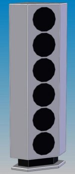
Here is an other option using six 12 inch drivers in a 7 foot tall main cabinet.
This might be a really good option for someone who would rather buy six 70 USD drivers instead of one 600 USD high end 18 mm X-max driver.
The dimensions of the cabinet are about 20 x 20 inches by 11 x 11 on the short sides and about 18.25 across the front baffle.
Hezz
This might be a really good option for someone who would rather buy six 70 USD drivers instead of one 600 USD high end 18 mm X-max driver.
The dimensions of the cabinet are about 20 x 20 inches by 11 x 11 on the short sides and about 18.25 across the front baffle.
Hezz
Attachments
JohninCR,
The maximum size of the cabinet is 7 feet tall in an 8 foot space. The above 12 inch array cabinet would be a maximum size but I would like a little smaller.
I will supply you with the specs for the Dayton 8 inch driver even though I think I will go with dual 12 inch sub. But I think that it would be both interesting for you to model and also might be a good solution for others. My mockups show that you can get 9 of the drivers mounted in an 7 foot tall cabinet.
Hezz
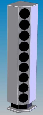
OK JohninCR,
If I was to do an 8 inch array I would need cabinet something like this. Again 7 feet tall and 18 x 18 inches on back sides. 11 x 11 on short sides and about 9.5 across front baffle.
Dayton drivers from Parts Express. Price: $20.15 EA (1-3)
Quantity Price: $18.65 EA (4+)
From the website:
"One of the main design goals at Dayton Loudspeaker is to create loudspeakers that can achieve high levels of performance at reasonable prices. Our import series of treated cone drivers are developing quite a reputation for having the best price/performance value available anywhere. Non-pressed treated paper cones, ASV voice coils, vented pole pieces, rubber surrounds, coated cloth dust caps, and excellent low frequency performance are just some of the features you'll find on these quality woofers."
Specifications: *Power handling: 60 watts RMS/85 watts max * Voice coil diameter: 1-3/8" * Voice coil inductance: 1.60 mH * Impedance: 8 ohms * DC resistance: 6.7 ohms * Frequency response: 29-3,000 Hz * Magnet weight: 15 oz. * Fs: 29 Hz * SPL: 88 dB 1W/1m * Vas: 2.04 cu. ft. * Qms: 3.23 * Qes: .44 * Qts: .38 * Xmax: 4.5mm * Net weight: 3.5 lbs. * Dimensions: Overall Diameter: 8-1/16", Cutout Diameter: 7-5/16", Mounting Depth: 3-3/4", Magnet Diameter: 4", Magnet Height: 1-1/4".
Hezz
Attachments
Hezz,
I was curious, so I took a look at parts express and chose the $21.50/ea if you buy 4 or more Pioneer 8", # 290-063 . I modelled
8 of them in a 6ft tall corner horn and all the different variations came up with very similar results so it would be hard to mess up and you might as well use the simplest to build. The cabinet itself would be about as small as you could get the drivers into (approx 12"x12" and 6ft tall) plus 2 narrow widths of plywood to form the 1st horn segment. It would take about 1.5 sheets of plywood.
Response:
HornResp shows over 100db of sensitivity from 24hz all the way out to 600hz. Response climbs from 100db at 24hz in a straight line up to 112db at 90hz where it stays out to 300hz. This gives you great flexibility. I believe the end result with room gain would be a pretty flat response, but if it's not you have so much extra output that you can EQ down the response to make it flat and or put a simple 1st order low pass filter and flatten the response. You could even run it using one of those $20 Sonic Impact Tamps and still have more output than you could dream of using.
Let's see one of these other guys come up with something even close for $170 in drivers that will fit in a 20"x20" corner and sound half as good and not end up with a bloated bass sound placed in a corner. For the price of just an amp for whatever they will come up with, you could buy the drivers to build a pair and drive them both with the sonic impact.
I think next time I go stateside, I'll get 16 of those pioneers for myself and build a pair of these for myself.
JohninCR,
When you model in HornResp do you have to have the horn enclosure shape or just the drivers. Even though the drivers are maybe 18 inches out from the wall it seems that given the cylindrical shape of the waveform the wall themselves will act as the horn. Though not ideal shaped.
In your opinion do you think that room gain would be sufficient to flatten out that steeply rising response a little.
Hezz
For SQ purposes I was thinking front horn, so you can't see the drivers. All of the output is coming from the horn. It could be a rear horn and have the drivers exposed, but having one side of the cone open to the air results in some added distortion (probably not significant in this case due to the drivers never really being pushed hard). With a rear horn there is also the issue of phase relationship of the front radiation from the drivers and the horn output. The horn length needs to be appropriate so the 2 outputs are in phase where the horn cuts off and the driver radiation takes over. That won't occur until you get out to 500hz or so and isn't really a factor if you use it as a sub.
The effect of the walls is already factored into the response. This would be designed specifically for a corner. If you pull it out of the corner, low end extension and output would drop significantly. With a normal type sub you should really factor corner loading into the design if that's the intended placement, otherwise they typically sound boomy in a corner.
Room gain depends on your room, whether it is completely closed, wall construction, etc. 12db over almost 2 octaves is not really a steep slope and could easily be offset by room gain, but it would be easy to make some adjustment after you get it in and see. That's a real benefit of having so much efficiency. eg if you want a fuller bottom end, just put an inductor in the path and roll the bass off at 6db per octave starting at say 30hz which puts you flat on paper. Then if that make you a bit bass heavy, just turn the horn slightly to raise the frequency of the final horn flare and or pull it slightly away from the corner and tune the bass to be just right for you. You can't do that with any other kind of speaker.
A picture is worth a thousand words
Hello John
Would you consider doing a screen dump of the Hornresp program. Your idea is indeed intriguing.
I have eight 15" woofers that are begging for a better place to live.
Mark
Hello John
Would you consider doing a screen dump of the Hornresp program. Your idea is indeed intriguing.
I have eight 15" woofers that are begging for a better place to live.
Mark
simon5 said:This is a subwoofer I made, when placed in a corner, using RatShack Meter with correction factors...
A single Shiva that's virtually flat from 125hz to 16hz at 108dB, with no EQ and the response is that flat?
I'll take that with a pinch of salt even with room gain 😉
You'd probably get a a flatish response in a larger room but then it certainly wouldn't be flat to 16hz at 108dB and no EQ or driver destruction for that matter.
I could work at the p-p required for a 12" at 16hz 108dB but I already know the answer and the Shiva isn't it.
Also why do you have the sub running all the way upto at least 125hz? Bet you can hear that sucker booming away in the corner 😉
I never have been able to get that screen capture to work, but here's the details:
s1 700 s2 1300 s3 3600
L1 50 L2 60
sd 1408
cms 1.60E-04
mmd 88.16
re 4 2 series groups of 4 parallel
bl 18.52
rms 9.92
le .25 ( I assumed .5 per driver due to 93db sensitivity)
VRC 16000
VTC 16000
While I'm sure it's not optimum, I've done this modelling before with arrays of smaller drivers, and changes made little difference, so construction would be forgiving. With these drivers, I tried this one with up to almost a 2m length with not much more extension, so I figured why not just keep it simple with a throat exiting at the side at the front. 1 segment anchored at the corner, then let the wall form the second segment. Of course for high SPL you'd want to use a piece of wood and bracing and construct the 2nd segment. Dividers would act as braces and make individual pathways with a much better width/height ratio.
- Status
- Not open for further replies.
- Home
- Loudspeakers
- Subwoofers
- Line array corner sub