Why not get yours and find out?
or maybe just build one, which shouldnt be too hard 😀
ehh, wait a minute, that sounds strange, Im confused now

My matched LDRs came with measurements. Why not get yours and find out?
Because I do not have this product and therefore I do not have this products measurements for left Right Channel balance. ...Yet more excuses and no measurements.
Cheers / Chris 🙂
Like this?😀or maybe just build one, which shouldnt be too hard 😀
ehh, wait a minute, that sounds strange, Im confused now
Last edited:
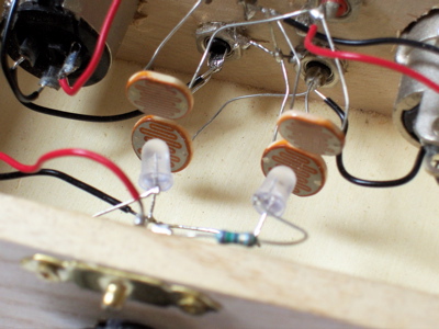
Or this one, another clone piece of crap, advertised as being new and superior, around the traps, one of my customers got it on loan from the maker and took this shot of the guts.
One can clearly see it's just bad a clone of a MkI Lightspeed Attenuator using series resistors and shunt really cheap LDR's.
Cheers George
One can clearly see it's just bad a clone of a MkI Lightspeed Attenuator using series resistors and shunt really cheap LDR's.
Cheers George
Attachments
Silonex NSL32SR2 is the part I use in L pad format, the same part used in this threads product.
I look forward to measurements being published for Left Right channel balance through full attenuation range
Cheers / Chris 🙂
I look forward to measurements being published for Left Right channel balance through full attenuation range
Cheers / Chris 🙂
Chris,
you are chasing a parameter that is relatively unimportant.
A 100k vol pot that is followed by a 100k input impedance resistor does not hold a constant load impedance for the Source feeding that vol pot.
That tolerable Zin as seen by the Source does not create added distortion, if the Source is adequately specified to drive the cables and load that follow.
Adding together the resistances of LDRseries & LDRshunt gives the equivalent to the vol pot resistance.
It does not matter that the total resistance seen by the Source is not absolutely constant nor does it matter if one channel is slightly different from the other. Try measuring actual dual track log pots. I have found they vary quite a bit in total resistance.
What matters for "stereo balance" is the resistance ratio of the Series : Shunt elements.
Go and do your homework and when you understand or get stuck come back and clarify where you then stand.
Yes, I agree.Accurate channel balance with LDR's is the the figure to strive toward, its the difference between a average LDR product and an exceptional one capable of accurate reproduction.
However, calculating the aggregate resistance for each channel and comparing those numbers tells you nothing about the channel balance. You need to calculate the attenuation of each channel and compare those figures.
Example:
L Series = 21700 Ohms
L Shunt = 1550 Ohms
aggregate = 23250 Ohms
Attenuation = 23.5dB
R Series = 22800 Ohms
R Shunt = 450 Ohms
aggregate = 23250 Ohms
Attenuation = 34.3dB
The aggregate resistances are exactly the same but the channel balance is out by more than 10dB. The left channel will subjectively be twice as loud as the right channel.
Chris,
you are chasing a parameter that is relatively unimportant.
A 100k vol pot that is followed by a 100k input impedance resistor does not hold a constant load impedance for the Source feeding that vol pot.
That tolerable Zin as seen by the Source does not create added distortion, if the Source is adequately specified to drive the cables and load that follow.
Adding together the resistances of LDRseries & LDRshunt gives the equivalent to the vol pot resistance.
It does not matter that the total resistance seen by the Source is not absolutely constant nor does it matter if one channel is slightly different from the other. Try measuring actual dual track log pots. I have found they vary quite a bit in total resistance.
What matters for "stereo balance" is the resistance ratio of the Series : Shunt elements.
Go and do your homework and when you understand or get stuck come back and clarify where you then stand.
Hi Andrew
Whilst this circuit uses a dual pot, mine uses a single, which is an advantage in avoiding imprecise tracking.
It would be interesting to see what this product does series shunt L vs series shunt R .
given that its purpose is a stereo audio device,
We could also start to see the effect of a fixed voltage and variable potentiometer relative to the photocell series/ shunt resistance variance.
Measurement, ..the more we know, the less we guess.
Cheers / Chris 🙂
Yes, I agree.
However, calculating the aggregate resistance for each channel and comparing those numbers tells you nothing about the channel balance. You need to calculate the attenuation of each channel and compare those figures.
Example:
L Series = 21700 Ohms
L Shunt = 1550 Ohms
aggregate = 23250 Ohms
Attenuation = 23.5dB
R Series = 22800 Ohms
R Shunt = 450 Ohms
aggregate = 23250 Ohms
Attenuation = 34.3dB
The aggregate resistances are exactly the same but the channel balance is out by more than 10dB. The left channel will subjectively be twice as loud as the right channel.
Hi Godfrey
Well explained Thank you 🙂
 Chris, with respect, I feel it is time for you to stop posting in this thread. It seems that you are here for one reason only, and that is to try and convince people that your offering is better. That is something you can do to your hearts content in your own thread, but is inappropriate here.
 As has been pointed out by a number of people, this is not a commercially oriented thread, however it seems it is your intention to make it such.
The purpose of this thread is for those that want to diy their own lightspeed, it is not a sales vehicle.
Consider this a warning
Today i've tested the LDR and with potentiometre @minimum still have some music, is not totally quiet. What i did wrong ?
I followed this article to build it DIY Lightspeed Attenuator - Passive LDR Volume Control (optocouplers)
Still is an audible enhancement over previous Alps pot.
The amplifier is a MyRef C also fresh finished project.
I followed this article to build it DIY Lightspeed Attenuator - Passive LDR Volume Control (optocouplers)
Still is an audible enhancement over previous Alps pot.
The amplifier is a MyRef C also fresh finished project.
Today i've tested the LDR and with potentiometre @minimum still have some music, is not totally quiet. What i did wrong ?
I followed this article to build it DIY Lightspeed Attenuator - Passive LDR Volume Control (optocouplers)
Still is an audible enhancement over previous Alps pot.
The amplifier is a MyRef C also fresh finished project.
Hi Autpi, glad you've also discovered the magic the Lightspeed can give.
As the circuit is posted by me, it is correct, the Lightspeed Attenuator will not go to complete silence it does have a very small amount of sound at min volume that can be just heard.
As the series LDR cannot go complete open circuit when no led light present and the shunt LDR cannot go complete close circuit when the led light is at it's brightest.
You could use your source pause or stop button if you need complete silence. Or you could make a mute switching arrangement that's be done somewhere in these pages.
Cheers George
I have two another issues and will try to solve it. First is that i have in a short movement of the potentiometre a huge increase of sound level.
Second i think i need a buffer as my freq response seems a bit changed. I will try a B1 buffer from Pass Labs.
If you have any sugestions i'm listening.
Second i think i need a buffer as my freq response seems a bit changed. I will try a B1 buffer from Pass Labs.
If you have any sugestions i'm listening.
Short movement can be caused by
1: Not having matched series/shunt (quad) sets of LDR's
2: Or way too much system gain.
3: Also this has the same effect, and I have had this done by careless customers, the source has been put into the output of the Lightspeed and the input of the Lightspeed to the amp/s.
As for the buffer question, it is defiantly better not to have one, what is your output impedance of your cdp/dac and what is the input impedance of your amps?
Cheers George
Last edited:
"Change of frequency response" compared to what? Your previous preamp?
I dont think a simple "frequency response change" on its own is a reason for a buffer.
How big are your interconnect cables? And what is your amp's input and you source's output impedance?
I dont think a simple "frequency response change" on its own is a reason for a buffer.
How big are your interconnect cables? And what is your amp's input and you source's output impedance?
My amplifier has an input impedance of about 100k and my sources wich dont know the output impedances are a Salas Simplistic RIAA preamp and a DAC wich is having on the analog following stage something like this
An externally hosted image should be here but it was not working when we last tested it.
I have an Audio Precision and it measures frequency response amoung other things. The Lightspeed is near flat frequency response (the only place it changes is at less than 100Hz where it drops off a few dB but not even 3, zero phase shift and near zero cross talk. Crosstalk is down nearly 100dB. The frequency response being different probably actually means 'more accurate' than the other pre.
Atupi with that output stage on your DAC and that input on your amp you do not have an issue with using a Lightspeed.
I have an Audio Precision and it measures frequency response amoung other things. The Lightspeed is near flat frequency response (the only place it changes is at less than 100Hz where it drops off a few dB but not even 3, zero phase shift and near zero cross talk. Crosstalk is down nearly 100dB. The frequency response being different probably actually means 'more accurate' than the other pre.
Unless you put in series coupling caps, the response on the low end should be flat to DC - it's simply a series and shunt resistor between the AP source and AP input. Or you are measuring the response of the AC coupling on the AP input.
This AP measurement will not correspond to anyone else's "real world" experience unless you have the same CD/DAC/Tuner/Phono preamp source output impedance, output coupling cap, cables, and input impedance and coupling cap on the next stage (usually an amplifier). Right?
And something also needs to be said about the Lightspeed's load presented to the source driving it. This will be dependent on the Lightspeed's volume control position.
As many of us have already observed, this load on the source from the Lightspeed can be relatively *LOW* compared to many other typical volume controlling devices - in the 500 to 1000 ohm range, or lower. In many cases this will be lower than the source output impedance, not the "times 10" number often recommended.
- Home
- Source & Line
- Analog Line Level
- Lightspeed Attenuator a new passive preamp