another simple solution is to insert a quiet/loud switch.
The switch bypasses a pair of 360k series resistors that reduce the current flowing to the series LEDs. Completely out of the audio signal stream.
The switch bypasses a pair of 360k series resistors that reduce the current flowing to the series LEDs. Completely out of the audio signal stream.
another simple solution is to insert a quiet/loud switch.
The switch bypasses a pair of 360k series resistors that reduce the current flowing to the series LEDs. Completely out of the audio signal stream.
Cool idea! I need to think about this one. Surely though, it changes the Zo by quite a lot. How does the downstream amplifier like this?
Karl
leaving the 360k in circuit is specifically for low level listening.
The output impedance of the signal side (when listening to low level signal) is largely determined by the Shunt LDR. The high value of the Series LDR hardly affects the impedance.
The output impedance of the signal side (when listening to low level signal) is largely determined by the Shunt LDR. The high value of the Series LDR hardly affects the impedance.
leaving the 360k in circuit is specifically for low level listening.
The output impedance of the signal side (when listening to low level signal) is largely determined by the Shunt LDR. The high value of the Series LDR hardly affects the impedance.
The attenuation for the T attenuator at Zo=6k tops out at 88dB when R2=0. I need to rewrite the spreadsheet to allow different resistor values that would result in higher attenuation, even if the price is a higher Zo. But I'm guessing that 88dB is practically silent, isn't it?
Karl
What difference does the value of the pot make? Everyone seems to use 100K but what if I use 50k or 10k?
a low value pot can only put a low value resistance in the circuit formed by the regulated voltage source and the LED.
That results in a higher value of minimum current through the LEDs.
That reduces the range of attenuation available from the LDR/LED combination.
That results in a higher value of minimum current through the LEDs.
That reduces the range of attenuation available from the LDR/LED combination.
a low value pot can only put a low value resistance in the circuit formed by the regulated voltage source and the LED.
That results in a higher value of minimum current through the LEDs.
That reduces the range of attenuation available from the LDR/LED combination.
Thanks for the explaination.
I want to use a digital pot to control the LDR but can't get a log one that is the right value so would there be any problem with using a 100k linear digital pot with a resistor across the input like this?
Last edited:
Thanks for the explaination.
I want to use a digital pot to control the LDR but can't get a log one that is the right value so would there be any problem with using a 100k linear digital pot with a resistor across the input like this?
Hmm, what would the ultimate curve look like after you combine the S-curve with the non-linear curve of the LDR module? Have you tried graphing the composite?
Karl
Hmm, what would the ultimate curve look like after you combine the S-curve with the non-linear curve of the LDR module? Have you tried graphing the composite?
Karl
Not sure, only ordered my LDRs yesterday! I'll have a play when they arrive. With a 256 step digital pot there would be room to adjust the resulting curve in software. I'll be controlling the digital pot via I2C from an ardunio.
That will work but you will want to make sure your wiper can handle the power.
Oh good point. I can't find one that takes more than 1mA. Useless!
Remote control for the "Lightspeed" LDR configuration designed by George
Hello maxw
That's why I designed the Voltage Controlled Current Source (VCCS) module with an Infra Red interface for remote control. It can be configured to deliver up to 20ma to the LDR LEDs. It has volume and balance control from the use of front panel push button switches on your preamp, or an Infra Red remote controller and one VCCS user has also interfaced a microcontroller to the serial ports on the DS1802. It can also be set up to run LDRs in balanced signal mode by modifying the voltage relationships in the voltage bias chain.
I can now supply very low noise discrete replacements for the TL431 shunt regs in the bias chain and for the 12 volt series reg powering the 12 volt supply.
Regards
Paul
Hello maxw
Oh good point. I can't find one that takes more than 1mA. Useless!
That's why I designed the Voltage Controlled Current Source (VCCS) module with an Infra Red interface for remote control. It can be configured to deliver up to 20ma to the LDR LEDs. It has volume and balance control from the use of front panel push button switches on your preamp, or an Infra Red remote controller and one VCCS user has also interfaced a microcontroller to the serial ports on the DS1802. It can also be set up to run LDRs in balanced signal mode by modifying the voltage relationships in the voltage bias chain.
I can now supply very low noise discrete replacements for the TL431 shunt regs in the bias chain and for the 12 volt series reg powering the 12 volt supply.
Regards
Paul
That's why I designed the Voltage Controlled Current Source (VCCS) module with an Infra Red interface for remote control. It can be configured to deliver up to 20ma to the LDR LEDs. It has volume and balance control from the use of front panel push button switches on your preamp, or an Infra Red remote controller and one VCCS user has also interfaced a microcontroller to the serial ports on the DS1802. It can also be set up to run LDRs in balanced signal mode by modifying the voltage relationships in the voltage bias chain.
Nice. Got a shematic or a link?
Remote control for the "Lightspeed" LDR configuration designed by George
Hi maxw,
The application notes are shown on post 2738 page 274. I have boards in stock if you decide to build.
Regards
Paul
Hi maxw,
The application notes are shown on post 2738 page 274. I have boards in stock if you decide to build.
Regards
Paul
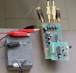
Got my VCCS LDR running...
I can recommend maximus's VCCS LDR control boards with the infrared remote- very well thought out and pcb's are top notch.
I have been using it for a 8 months now- works like a charm! Even with matched LDR's, I get a slight shift of image to the left on low volume. Having the balance controls on the remote has been very useful to compensate. I'm using a small Lamdba 15V power supply I found at a surplus shop.
pre>VCCS LDR>amp.
A big thanks to George, udaily and maximus. The most transparent volume control I've ever had!😀
-Kent
Attachments
Remote control for the "Lightspeed" LDR configuration designed by George
Hi Kent,
I see you are following the open plan approach. Mine is the same. Saves a lot of metal bashing. I'm pleased you are enjoying the results.
Regards
Paul
Hi Kent,
I see you are following the open plan approach. Mine is the same. Saves a lot of metal bashing. I'm pleased you are enjoying the results.
Regards
Paul
Ha! Yes, the 'plein air' approach.. you should see the remote! 🙂 I found a little metal chrome razor box that I might squeeze the remote in. The VCCS is waiting for me to finish the salas phono stage, where they will both share a case.
LDR Imp curves
Hi,
as I´m driving a fairly low impedance amp (10k7) with those LDRs, I wonder if it would be better to lower the total impedance of the LDR attenuator by paralleling LDRs in the signal path, e.g. paralleling the serial LDR. Or , maybe paralleling serial and shunt LDRs (total of 8 LDRs i.s.o. 4)
I tried to predict the impedances (see below) . What would be most important to look for ? eg.flat curves (=constant impedance at the amp or source over the attenuation range), or equal number of shunt/series LDRs to compensate distortion ?.....
Cheers, Frank
Attachments
fbee,
suggest you keep it "standard" and use a buffer - my amp offers a 9kR load and the 'symmetrical B1' buffer does a rather good job - needs a good power supply.
suggest you keep it "standard" and use a buffer - my amp offers a 9kR load and the 'symmetrical B1' buffer does a rather good job - needs a good power supply.
Hi James,
yeah, already envisaged the DCB1.
But as George mentioned, "no buffer" should be desirable, maybe I have to try different things:
yeah, already envisaged the DCB1.
But as George mentioned, "no buffer" should be desirable, maybe I have to try different things:
- Leave the classic 4 LDR setup (alredy sounds great) or
- Modify the input imp from 10k7 to ca. 50k and/or
- Modify the LDR Att total impedance by paralleling LDRs or
- use a DCB1 (without capacitor in the signal path
- Home
- Source & Line
- Analog Line Level
- Lightspeed Attenuator a new passive preamp