Hi fbee, Interesting to try if someone has the time here, in my case cost would be a issue, but then this would be counteracted by not having to be so critical on matching, and then how would it sound, interesting, wish there were more hours in the day.
As for the remote, have not tried this, again time constraints.
Cheers George
As for the remote, have not tried this, again time constraints.
Cheers George
Audiodiy1
Nice job. I am glad its working well for you.
Frank
I am using 3 LDRs at each position right now. Well until yesterday with I removed one each from Shunt. I dont hear a sonic benefit. Maybe maybe a bit richer but I have to AB it some more to be sure. Unsure about THD.
Never tried or heard of anyone trying what you are talking about for control.
BTW I guess Dartzeel uses some 100 LDR per channel .
Uriah
Someone was asking about Balanced LDR sets. I have a few. Let me know if you are interested by PM or email.
Hi,
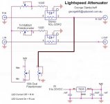
I was wondering if this would work:
http://www.diyaudio.com/forums/attachment.php?attachmentid=163463&stc=1&d=1269112786
I was wondering if this would work:
http://www.diyaudio.com/forums/attachment.php?attachmentid=163463&stc=1&d=1269112786
Attachments
I wondered the same thing. Wondered if I could use ONE LDR for shunt and only have to match the series pair.
It works but the soundstage collapses into a tiny point right in the center of the two speakers.
Uriah
It works but the soundstage collapses into a tiny point right in the center of the two speakers.
Uriah
Hi,
I was wondering if this would work:
http://www.diyaudio.com/forums/attachment.php?attachmentid=163463&stc=1&d=1269112786
Trouble being you'll need one pot for the series ldr DC voltage control and then another pot for the shunt pot to earth. How will you logarithmically control the two and keep channel balance at the same time.
It will become even more user unfriendly than my production Lightspeed Attenuator is that has separate L & R volume controls, which is an option that some customers buy (because they have system imbalances) But is a pain to use, just like the Audible Illusions 3a Preamp I used to have.
Cheers George
Thanks for the replies George & Uriah,
How about a tri or quad pot?
One group for the LDR's and two others for shunts? I'm thinking the shunt isn't as critical and might be fine with regular pot instead of LDR's. Plus, no matching and can go to 100K.
Of course if it doesn't sound as good then no point...
All too much, and series + shunt quad matched LDR's as I do them, sound better than my old resitor+ldr or ldr+resistor MkI Lightspeed Attenuator. Just go to the trouble of matching quad set's and you won't look back.
Cheers George
Cheers George
If the shunt arent matched really well this will throw your balance from Left to Right off more dramatically at regular listening than if your series are not as well matched. Its the math that screws it up.
I am not saying dont do it. It would be fun and educational. Then you could remove to gangs of the pot and just run matched shunts with the second gang and see what the difference is. If you are prone to experiment this might be fun. If you just want the best sound and no confusion and consternation go with matched quads.
Uriah
It's time...
I've ordered a VCCS for balanced operation from Paul and matching LDRs from Uriah.
Plans for a balanced buffer is in the pipeline.
I've ordered a VCCS for balanced operation from Paul and matching LDRs from Uriah.
Plans for a balanced buffer is in the pipeline.
LDR Remote Control
This is my first posting on this topic. I want to thank George and Uriah for their efforts in bringing this LDR concept "to the surface" and continuing to make their expertise and parts available to the DIY public.
No question in my mind that this concept is the way to go and I am going to incorporate it into my own home preamp. However a requirement I also have is that at least gain and input switching be remotely controlled.
Let me offer this idea: Check out the Lite DIY IR remote control DIY prodicte MV-4 and MV-06: roughly $60 on Ebay delivered to the US
:
6 way Audio Remote Control DIY kit PCB w/parts /MV-06 - eBay (item 290414602945 end time Apr-15-10 14:29:23 PDT)
I have used this in it's "unmodified form" before and it works well. Basically it includes a remotely controlled motorized potentiometer and input switching - either 4 or 6 channels. It looks as if it may "easily" be adapted to use the LDR's as the "stock" potentiometer has (quantity) 4, 100Kohm decks and the input switching relays have DPDT contacts. The attachments to each deck of the potentiometer could be wired out to control a pair of stereo shunt/series LDR attenuators, and the relay contacts used to control two LDR's for input switching (The input signal would first "see" a shunt LDR then go through a series LDR - you control these LDR's by "slamming" them either on or off) - the output of each of these 4 input stages would then be paralleled and fed to a high quality (high input impedance) buffer stage for isolation and impedance transformation.
I must mention that the MV "kits" consist of "just" pre-assembled boards and interconnecting cables. You have to supply a DC input voltage, mount and wire everything so I'd have to opine that this project concept is for "advanced" experimenters.
Cheers
Charles
Charles,
Your'e right. A remote is a nice way to go. Maximus has developed a remote and power supply for the Lightspeed circuit. No its not already built but it sure is high quality.
The switching wont work as you have envisioned. LDRs go to about 50 Ohms minimum. Lower than that is not to healthy for them. To slam one on to 50Ohms to ground wont drop your min volume to anything like minimum when you want to listen to a different source. So you would have to parallel a lot of LDRs to act as one to get down to just a few ohms or use a relay to ground.
Uriah
Input switching
Uriah,
I understand that the shunt LDR's resistance cant/doesn't go to zero and will pass some signal BUT I'm also suggesting another LDR, say a -32SR3 in series after the shunt. When turned off, the spec sheet says it presents a resistance around 25M ohms, so with the two LDR's we now have a "potentiometer" with the "gain" turned all the way down. Opposite happens when you switch the LDR's in the other direction - signal sees no shunting resistance and only 60 ohms or so series R. OR am I missing something here
Charles
Don't assume these unused relays go to ground when not in use, they may go open circuit when not in use, and only the one used is closed circuit, if so then the Lightspeed circuit can be used as normal. If not a couple of circuit track mods can make it work this way.
Cheers George
Cheers George
Most of the SR2 go that low to. My bet is that most of the SR3 are actually the same thing. Just that they are confirmed to go that low. Anyway I could be wrong.
What you said and what George said both make a lot of sense and given that the relays work the way George mentions I dont see why it couldnt work. Its a good idea and I hope you build and post here about your build.
Uriah
What you said and what George said both make a lot of sense and given that the relays work the way George mentions I dont see why it couldnt work. Its a good idea and I hope you build and post here about your build.
Uriah
maximus> I'm doing some psu calculations regarding the balanced VCCS. (22-24VDC)
How much current is needed? (How many A?)
How sensitive is the VCCS to ripple? Is it filtered in the module?
How much current is needed? (How many A?)
How sensitive is the VCCS to ripple? Is it filtered in the module?
Now some numbers...
6.3VAC -> Voltage quadrupler -> 25.2V - 2.24V (max voltage drop @ 160mA) = 22.96VDC with a LOT of ripple.
(beefy caps, 35V@10000uF)
Just playing with numbers...
6.3VAC -> Voltage quadrupler -> 25.2V - 2.24V (max voltage drop @ 160mA) = 22.96VDC with a LOT of ripple.
(beefy caps, 35V@10000uF)
Just playing with numbers...
Last edited:
Hi,
I think you can use that voltage drop under load to give a rough indication of ripple.
The Vripple <= 2 * Vdrop, i.e. 2.24Vdrop gives Vripple <=4.5V.
$.5Vripple is actually a peak tp peak measurement. I find that a DMM reads approximately 1/3 *Vpp of ripple.
You should be able to read Vdc=22.96Vdc and Vac ~1.5Vac.
Readings of this order would confirm my guesstimates.
Now V minimum is Vavg - 1/2 Vripple, i.e 22.96 - 2.24 ~20V at the bottom of the ripple trough.
Regulate this down to 12V to ensure that the 12V has no dropout when mains goes lower than nominal.
Then regulate the 12V down to 5V to power the LED in the LDRs.
If this answer on LDR power supply has nothing to do with your enquiry, then hard luck.
Last edited:
It really was a worst case scenario I painted. More realistic figures I think ->
Due to series shunt attenuation we should have something like 40mA tops in a balanced configration.
That would result in a maximum 0.56V drop and iirc 24.92VDC + 0.28VAC.
(Villard Voltage multiplier)
I'm going to ue the VCCS by the way, not just the LDRs.
Due to series shunt attenuation we should have something like 40mA tops in a balanced configration.
That would result in a maximum 0.56V drop and iirc 24.92VDC + 0.28VAC.
(Villard Voltage multiplier)
I'm going to ue the VCCS by the way, not just the LDRs.
Forgot to ask - LDR "power handling" capability
Has anyone checked out what I'll call the power handling capability of the LDR. What I mean here is - if I want to use it in, say a shunt device for input switching, depending on the source I could be subjecting the LDR to some "abuse", maybe even direct current resulting from DC offset.
Thanks
Charles
- Home
- Source & Line
- Analog Line Level
- Lightspeed Attenuator a new passive preamp