ehh, I suppose they would just be wired like a strereo pot, right
That's what I have tried, but I am not getting straightforward L&R volume control. So I asssume that the wiring would have to be different to get independent L&R control.
I am going stick a few wires here and there and see if I can get a few sparks and just maybe some balanced sound 😀
That's what I have tried, but I am not getting straightforward L&R volume control.
Right
When Uriah suggested to use mono pots, I actually supposed it would be two mono pots
I was quite surpiced when it was suggested to be only one mono pot
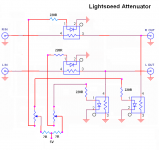
When looking at modified schematic I just made, it still look different from the original stereo pot version by George
Theres coupling between left and right, through the 5V connection
With a stereo pot, this connection is asymmetric and through resistor
When one goes up, the other goes down
With monopots it varies symmetrically
I have made a suggesion of two fixed resistors at the left/right 5V supply connection
Dont know if a balance pot would help in that position, as it would also have asymmetric function
Maybe theres something we dont see
Uriah(and other members) have worked seriously on this issue, and have been fair to conclude that its best to use the original by George
Attachments
Last edited:
Wouldn't you need four (4) mono pots to do separate left and right control of level and impedance?
Two (2) stereo ganged pots for just left and right level control, and one (1) as designed for simultaneous channel level control?
Side note, I got all the parts to make my PCB's and will assemble them this weekend. (I hope)
Two (2) stereo ganged pots for just left and right level control, and one (1) as designed for simultaneous channel level control?
Side note, I got all the parts to make my PCB's and will assemble them this weekend. (I hope)
The way Tinitus shows it would control L and R.
If you were to instead use one pot, like in Tinitus schematic, to control Series and the other pot to control Shunt then you would control impedance.
Or you could use 4 and control L and R and impedance.
Or you could use 2 for impedance with a balance pot on one.
Or you could use 2 for L and R and a extra pot on each to control impedance.
But its just easier with a dual gang audio taper and a small panel mount pot for balance.
Uriah
Heres a new 500K stereo pot, but its relatively expencive, considering high quality is not needed fore this
On the other hand, we are rewarded with the best there is, and still cheap, so what
Still, 250k Alps cost much less
http://www.hificollective.co.uk/components/potentiometers.html
Though I have seen cheaper 470K stereo pots
Whats the present status on needed pot impedance ?
What happens if we use smaller value stereo pot wired as original, but with much bigger series resistors on all LDR ?
Last edited:
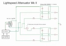
I have been using dual mono for some time with the wiring as described by Tinitus - effectively splitting a stereo pot into to two. I hope the attachment make sense.
Alan
Now that makes so much more sense. Thanks.
Tinitus,
Just use a 100k dual log pot as George has said.
If you need to increase impedance then use 10-30R resistor inbetween power supply and the 100k dual log pot.
I saw a 25R 3W pot at radio shack today that would do a great job for that resistor. As you turn that pot the impedance will rise.
Try it with 100k first, just as Georges circuit is. IT might be perfect for you.
Uriah
Tinitus,
Just use a 100k dual log pot as George has said.
Ok, thanks
That certainly makes things much easier
So the previous talking about 500k pot fore 500k ohm LDR(mine), and new orders fore 100k LDR to avoid 500k pot now belongs to the past, and was due to NOT using a stereo pot
Im just a bit confused and want to be certain
I am just matching them all now to 100k. Its to much hassle to fiddle with 500k or 200k or whatever. We have a way to control impedance so lets keep it simple. 100k dual log pot as always then if you need higher impedance just mess with the 10-30R resistor and voila you have the impedance you need.
So, use 100k. If its impedance is to low AFTER you try 100k then use the little resistor in series with the 5V. Just putting all 4 LDRs in the circuit will boost the impedance because of voltage drop across the LEDs so it might be fine with no series resistor. So start there. Dual log 100k.
Uriah
So, use 100k. If its impedance is to low AFTER you try 100k then use the little resistor in series with the 5V. Just putting all 4 LDRs in the circuit will boost the impedance because of voltage drop across the LEDs so it might be fine with no series resistor. So start there. Dual log 100k.
Uriah
VCCS Lightspeed working
Hi Paul-
Thanks for the design and the boards, I finally completed my attenuator. All is working properly! More feedback later, but it works like a charm! I have some questions-
1) I found a nice little wall wart for power, but it is 15.5 volts. Assuming the output of this wall wart is reasonably clean, would it be safe to power the VCCS board with 15.5vdc instead of the recommended 15vdc?
2) I would like to use two analogue level indicators (using old mA meters). Where would be the best place to sample a voltage level to drive a buffer for the meter? the W0/W1 points of the Dallas chip?
Thanks again to Paul, udaily and George!
Cheers- Kent
does the 15.5Vdc vary with mains supply voltage?1) I found a nice little wall wart for power, but it is 15.5 volts. Assuming the output of this wall wart is reasonably clean, would it be safe to power the VCCS board with 15.5vdc instead of the recommended 15vdc?
What is the output voltage when mains is lowest and when mains is highest?
Now load up the supply and check the lowest and highest output voltages.
Lightspeed remote control
Hi Kent,
Pleased you are up and running.
Andrew is right. You need to check if the wall wart is regulated or not as mains voltage changes can vary the output voltage of unregulated DC supplies. If then regulator runs a little warm fit a clip-on heatsink.
If you use the W0/W1 points for a reference make sure the buffer has a high input impedance and you will have to be careful where you reference the buffer circuit to on the VCCS board. Post your buffer/meter circuit on here and I will advise you about interface.
Regards
Paul
changing attenuation range
udailey, AndrewT, woodturner-fran -
I have been following your suggestions/adventures to change the attenuation range of the LSA.
Uriah: I've tried 10-30R (and even more) between the 5v and pot with little joy.
Andrew: Tried a higher value pot (mine is 500k so tried 1M) again no improvement.
Curiously though, I have a 22k pot as a trimmer on the louder channel and turning this full travel is the biggest attenuation so far.
My next experiment will be to try a dual 100k pot ( after the 500k pot ) wired as trimmers for each side and see if this gives a scaling that allows greater travel on the main 500k pot.
Any advice appreciated 🙂 any warnings too 😀
Tried a higher value pot (mine is 500k so tried 1M) again no improvement.
Uriah has several times stated that we should use dual gang pot, and that theres no need to use 500k
And no resistor between supply and pot
Maybe slightly bigger resistors before LDR
As I understand it, the previous request fore 500k pot was due to some faults from using single gang pot
Dual gang down to 100k should be fine, no matter what kind of LDR you have
The pot connections are reversed, so suppose log pot is ok
A log pot may be exactly what you need
#
Last edited:
I'll post this circuit again, it is exactly the one used for my production Lightspeed Attenuator, if you follow it and use the NSL-32SR2S x 4 matched, you will not have any troubles at all with volume range, the lowest volume setting will be just a whisper and the highest will be the full output of the source and probably will take out your speakers.
Cheers George
Cheers George
Attachments
- Home
- Source & Line
- Analog Line Level
- Lightspeed Attenuator a new passive preamp