Very neat Francis keep up the good work, can I suggest you do one more thing, I have with the production Lightspeed Attenuator found that it is a must to thermally couple all the ldr/led units together.
I do this by potting all 4 together in hard ski base wax, once everything has been tested calibrated.
And then after the wax has cooled to room temperature re-calibrate for a final time as the wax does sometimes change things a little.
The other thing I noticed is that some of the LDR's are not ambient light proof they, leak in ambient light from the rear of the ldr side, I believe they have not used enough black pigment in the housing mix. The potting with the wax also cures this manufacturing problem.
Cheers George

Very cool project Rellum!. Looks like a lot of fun.
Probably more fun than matching!! :O This is taking ages.
Ordered 25 from Allied. Sorted. Of course they did not come sorted, or even close. Hint, after reading the thread, if you want to buy some to match dont buy sorted. It seems that most people end up with unsorted batches.
Uriah
Probably more fun than matching!! :O This is taking ages.
Ordered 25 from Allied. Sorted. Of course they did not come sorted, or even close. Hint, after reading the thread, if you want to buy some to match dont buy sorted. It seems that most people end up with unsorted batches.
Uriah
Now that I am measuring... almost done with first of 3 tests... I am unsure what is a good match for the LDRs. Could someone post some good examples of measurements they got that are working out well?
I have one set that has passed the first test with the exact same ohmage and several sets that are within one or less ohms down in the 38ohm range.
Hope someone can please post a few examples of their three or more tests. I dont know if exact or 1% or 10% is okay.
Thanks
Uriah
edit: obviously exact match is great but how far off is okay?
Well, through with second round of testing LDRs and onto the third round of testing.
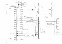
Made up a board layout while I am running tests. Here is a GIF. I will probably etch a few of these today. Comments are welcome.
The board uses terminal blocks which could just as easily be removed and wires soldered directly in. On the side of each block is a hole which is no longer used but I figured leave it as its doing no harm and could be used for putting a cap across the resistor.
Uriah
edit: There are two trim pots but if I want only one or none I can just short the connection. The terminal blocks for the main pots each contain a ground which is overkill but I didnt want to use a 3 terminal block.
Attachments
Here is my data on 24 of 25 LDRs tested. One of them was fried when it got to me.
I tested with a 3V battery with the following resistors in series with the + side of the battery.
100R
9960R
22000R
47000R
I tried to upload but it looks terrible all compressed. Here it is a little better:
http://picasaweb.google.com/udailey/LightspeedAttenuator#5292315840126431810
I think there are several good candidates in there. Many track a hundred or so ohms away from each other but they still have the same curve. At least all datapoints are in similar proportion on several of them. So that makes me think that the 1k pot will work well. I think I will actually use a 1k pot as a balance as suggested instead of using a trimpot. I do have a 10k 10 turn precision Helipot that I might try instead in case for some reason I want to really mess with the balance, like when setting the speakers up properly in my listening room.
Uriah
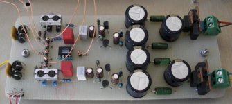
Well, the first PCB for the lightspeed is goofed up. Notice that one of the resistor legs goes to ground when it should go to the neighboring resistor. I fixed that before trying it out.
My supply works well. I get 4.96VDC with no transformer and powering the supply from mains power. Nice and easy. When I connect this supply to the potentiometer I get 5.06VDC out of the potentiometer for some reason. Odd. I hooked an LED with 100ohm in series to the power supply to test it. It does vary the intensity of the LED. Not super smoothly though, it seems nice most of the way but some places have a quick increase in brightness.
Something went wrong though and its not making sense. Hope you guys can help out although after watching this thread the last week it seems no one is home. Anyway, If you check out the datasheet for my power supply you will see how I made it. Its exactly as on the sheet :
http://www.rohm.com/products/databook/pm/pdf/bp5034d5.pdf
So, I hooked this up to the pot and then put the DMM on the resistor part of the LDR. I get nothing. Never registers that there is a resistor in there at all as I am varying the current with the pot.
The Silonex datasheet says max 2.5V but we are putting in 5V is this right? Must be.
If somone could look at my layout and figure why the resistors are not getting any light or why the LEDs might not be turning on let me know. I have tested and I do have 5V coming to them. GROUND is actually COMMON/NEUTRAL but 5V is 5V dont think that is the problem.
Uriah
Well, I had polarity reversed. So now the LDRs are varying their resistance while I turn my potentiometer. Sweet 🙂 I was worried something bad had happened.
Uriah
Uriah
Hooked it up to my Harmon Kardon that is now only used to test stuff. This way if I had something reversed the HK would make sure that the power was still very low going to the speakers.
It did attenuate the volume when placed between the CDP and the HK.
So I hooked it up to my MYREFC dual amps and placed one junk subwoofer on one of the channels, nothing on the other. Tested and it worked.
Hooked up the Audio Nirvana 12" BR cabs and the MyRefC and the Lightspeed. Works great! Of course my daughter is watching "The Super Readers" and wont entertain a listening session right now. Will have to do that later.
And YES it is very very loud at 1/3 of a turn.
Uriah
Okay,
I usually get pretty excited when something I DIY works. Nothing new today. I am just ecstatic about this pre!
The sound stage is really wonderful. Everything is clear/transparent. Cymbals sound like cymbals as another DIYer put it. Its as if you can hear that there is nothing to hear in between the instuments. Very nice. This one stays! This is far better than any of my carbon pots. Its better than my wirewound, not leaps and bounds better, but definitely better. Better than having the B1 on the amps? Well, yep.. its better to me. So far the best pre even better than the dale based stepped pots. Loving it.
I like to listen to "I want my MTV" really loud for a new piece of equipment to be introduced to the rest. AWESOME! Always is but today its was amazing as well.
You guys are going to enjoy this pre if you build it.
Ri
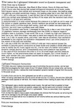
Good to see you finally reached Nirvana Uriah, I've been watching your progress building your own Lightspeed and you have truly diy'ed it, on your own. It's great to reap the benefits of battling through the unknown and reaching a height of sound quality as you have expressed.
Below is what I have found over 30 years and why it sounds the way it does, it was posted before but is buried way back in this thread somewhere so here it is again, these two docs get sent out with every Lightspeed Attenuator I produce for customers who purchase them.
Cheers George
Below is what I have found over 30 years and why it sounds the way it does, it was posted before but is buried way back in this thread somewhere so here it is again, these two docs get sent out with every Lightspeed Attenuator I produce for customers who purchase them.
Cheers George
Attachments
Thanks George. It really is fantastic and I have not heard anything that can touch it. I had a great little chip amp built with wirewound pots as passive pres and I really liked it. Something happened with my eternal poking around in the amp case. Next time I switched it on it screamed and quit. For the last half a year I have been trying to get the great sound back. Chip amp after chip amp didnt sound the same. I recently organized a group buy for the MyRefC kits and after building two channels was convinced that it was a really good amp and had some features I enjoyed that my previous chipamps did not have. But the clarity I had before wasnt there. Well, it is now. My system sounds better than it ever has.
Thanks again George.
Uriah
Thanks again George.
Uriah
LDRs Matched Sets
Guys/Gals
I bought 125 LDRs. Was thinking on a equalizer but its not going to happen.
I have many matched sets and would sell them to you if you are interested. Email me for 4.
Process:
I placed them in a jig and ran voltage in through 100, 9.96k, 22.1k, 47k resistors each for about 10minutes placing the next resistor in series before removing the previous to make sure the LED never turned off. I wrote down each reading and entered into a spreadsheet. Made a graph and selected the best matches. I bagged and tagged each set of two pairs and am now halfway through putting each set of pairs into another test jig to listen to them and make sure that they are in fact matched. So far I am having stellar success with great matching.
After including the work on building the jigs, testing, entering data, testing again, placing and removing from jig I estimate each LDR has taken me well over an hour to test. I think I need a more efficient method!
If you are interested let me know by email.
Uriah
Connectors recommend
Hi
Can you recommend RCA connectors , hook-up wires and low capacitance IC cables for this excellent preamp?
Thanks
Hi
Can you recommend RCA connectors , hook-up wires and low capacitance IC cables for this excellent preamp?
Thanks
I am sure george has a preference and there are lots of other builders but here is my suggestion:
Build the power supply and incorporate the 100k dual pot, the trimpot/s, the 100ohm resistors in your power supply. Then solder your LDRs directly to the amp inputs AFTER the RCA connectors that go to your amp. So the LDRs will be between the RCA and the amp, prefferably right ON the amps inputs. Then put the little supply either outside or at front of the amp. Run power and 0v from power supply to the LDRs on long wires, twisted, shielded, whatever..
No extra RCAs, no extra interconnects which are both better options than new and expensive ones plus the LDRs are sitting right there on the amp.
Uriah
Lightspeed remote control
Hi Folks,
So far only 10 people have expressed interest in the VCCS remote control board/module for the Lightspeed. I can't believe that, like George, you are all sitting next to your volume control and would not therefore find a remote control for volume/balance of the Lightspeed useful. I need to see another 10 interested persons before I instigate a printed circuit board order.
I can report that there have been no operational anomalies occuring since installation in my system. The system is in use daily and the LDR's are burning in nicely.
This is, without doubt the finest volume control I have crossed paths with. It's uncanily adept at resolving subtle information even during large dynamic signal swings and the image remains stable as well.
Regards
Paul
- Home
- Source & Line
- Analog Line Level
- Lightspeed Attenuator a new passive preamp