Bgt said:
BTW sound is very nice only at very low levels the sound gets duller than from a DACT stepper.
Strange, I would expect it to be the other way round 😕
mine sounds grrrrrrrreat!
As well as Paul Hynes VCCS (currently building) I have made a LightSpeed as per GeorgeHifi using Uriah's diagram. Although I have not yet waxed the LDRs I have the device in my system - it produces a very low-level sound at minimum - just to let me know it is on - and a really workable range for the volume.
To put it into context I am using a computer front end (cics cMP2) into the LightSpeed into a Peter Daniels Patek style amplifier into Gedlee Abbey (clone) speakers, all interconnects are by Grover Huffman.
The result is a very beautiful sound - lots of detail - both instrumental and musical - and a well rounded bottom.
Without a doubt this is the best my digital system has ever sounded.
Am I happy?
I should, of course, have thanked Uriah for his matching exploits and documentation / posts which have helped me enormously. I am waiting for the next lot of LDRs!!
Above all thanks to GeorgeHifi for publishing details of his excellent product.
Regards
Alan
Above all thanks to GeorgeHifi for publishing details of his excellent product.
Regards
Alan
I would also like to thank George very much for sharing his work. I am in Australia and bought 10 LDR's (sorted) from Crest Components (Aus), cost AUD$70 delivered. There was an extra $20 charge because I didn't meet the minimum order, so cheaper for more, but I didn't want more. For initial matching I used one DMM on diode test function to get a Vf and another DMM to measure the resistance, then went from there using the 100K pot at 9, 12 and 3 o'clock, (as George advised) looking for close pairs for series positions and close pairs for shunt positions, then pick the higher resistance series and shunt for one channel and the lower resistance series and shunt for the other channel, aiming for the most consistent voltage divider basically. Then I built it without the trimpot, ran 5V DC through both attenuators to see which channel needed the trimpot, put the trimpot in, adjusted up very nice, the calibration came out much better than expected. (I have a scope and sig gen, but was time limited and hoped the DC test would be good enough, with 5.00VDC input the range of output was 2mV to 4.99V).
So yes, I agree guys they aren't really matched very well at all, but it doesn't have to be rocket science either. Of the 10 OC's I got, there was a group of 5 reasonably similar and another group of 3 reasonably similar and the other 2 just way out there on their own. George's circuit works great, which could have taken any one of us weeks and/or months of tearing our hair out to get right. I don't have any probs with sound not going to zero, I have to turn it up a bit, due to lowish output NOS DAC. I can't really comment on the sound improvement unfortunately since I built it up with minor power supply mods on the DAC, but the end result is the sound is now cleaner/clearer and with deeper bass.
Good luck guys. Thanks George! I owe you one! Do you still run George HiFi, that was around in the early 80's in Sydney city wasn't it? I remember that name but it was 25 years ago...
Ian.
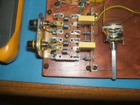
A pic of a tagstrip version, no trimpot fitted yet.
So yes, I agree guys they aren't really matched very well at all, but it doesn't have to be rocket science either. Of the 10 OC's I got, there was a group of 5 reasonably similar and another group of 3 reasonably similar and the other 2 just way out there on their own. George's circuit works great, which could have taken any one of us weeks and/or months of tearing our hair out to get right. I don't have any probs with sound not going to zero, I have to turn it up a bit, due to lowish output NOS DAC. I can't really comment on the sound improvement unfortunately since I built it up with minor power supply mods on the DAC, but the end result is the sound is now cleaner/clearer and with deeper bass.
Good luck guys. Thanks George! I owe you one! Do you still run George HiFi, that was around in the early 80's in Sydney city wasn't it? I remember that name but it was 25 years ago...
Ian.
A pic of a tagstrip version, no trimpot fitted yet.
Attachments
Sound going to zero?
You mean like muted?
I will just use a signal source switch, and have a position with no signal
But if you want only one source and no switch, like George does, then ofcourse that does not work
Your use of solder lugs look very neat
But if you want absolute optimum result I think the solder lugs could be an issue 🙄
But may be placed with the "magic stones"
So yes, I agree guys they aren't really matched very well at all, but it doesn't have to be rocket science either.
Good luck guys. Thanks George! I owe you one! Do you still run George HiFi, that was around in the early 80's in Sydney city wasn't it? I remember that name but it was 25 years ago...
Ian. [/B]
Yes, agree, some I feel are going over the top with the matching for channel tracking with all the electronics involved K.I.S.S.
My production ones >170 now have never had a single complaint with the channel balance with the way I match them, which is still a P.I.T.A. when your doing a few.
As for the 80's city shop, you have a good memory, less said the better about that little disastrous short term venture with the lease and the conman that owned it.
Cheers George
Lightspeed remote control
Hi Folks,
I managed to assemble a jig full of VCCS modules this Bank Holiday weekend. I will test them on Saturday next and start getting them in the post early next week. I will try and get some IR boards done as well. I should be able to continue progressing orders each Saturday and I expect to have all the outstanding orders fullfilled by the third week in June.
Regards
Paul
is it possible to use something like that in remplacement of the standard Lightspeed pot?
http://stiftsbogtrykkeriet.dk/~mcs/Remote/index.html
http://stiftsbogtrykkeriet.dk/~mcs/Remote/index.html
Hi Paul-
I rx'ed my brds this week here in the US. Thanks again.
Was the BOM completed and and if I recall correctly there was a version for Mouser. May I request it be posted again?
Anyone build Pauls PCB's yet? Looking for suggestions / ideas on remote enclosures and such..
I rx'ed my brds this week here in the US. Thanks again.
Was the BOM completed and and if I recall correctly there was a version for Mouser. May I request it be posted again?
Anyone build Pauls PCB's yet? Looking for suggestions / ideas on remote enclosures and such..
Hi
Are there any risk of lightspeed att could generate DC on output
Or is it sensitive to any DC from source

Are there any risk of lightspeed att could generate DC on output
Or is it sensitive to any DC from source
If you follow the diagram there is zero chance. If you put DC on the input it will for sure put DC on the output. The input and output for signal ONLY go on the long leads of an LDR. DC from the dual pot goes to the short leads which are the LED.
Uriah
Uriah
Thanks
I have just seen the double pots I mentioned ealier
You know, the stereo pots with 2 shafts
Channel balance adjustment and attenuator, in one
Its carbon though
btw, how is it going with our LDRs
Im in no hurry at all, just take your time 😉
I have just seen the double pots I mentioned ealier
You know, the stereo pots with 2 shafts
Channel balance adjustment and attenuator, in one
Its carbon though
btw, how is it going with our LDRs
Im in no hurry at all, just take your time 😉
All are now labeled and separated into batches of 12 then bagged into bags of 100. Today I am working on recalibrating the jig. Maybe will start testing this weekend, but again, no marathon testing this time. Its not a fun job, but you guys building these LSAs and going "WOW" is fun! 🙂
Uriah
Uriah
troystg said:Hi Paul-
I rx'ed my brds this week here in the US. Thanks again.
Was the BOM completed and and if I recall correctly there was a version for Mouser. May I request it be posted again?
Anyone build Pauls PCB's yet? Looking for suggestions / ideas on remote enclosures and such..
This is the BOM I produced - the Farnell list has two problems - you have to buy 50 resistors at a time and the 10M does not fit into the board.
http://www.diyaudio.com/forums/showthread.php?postid=1827830#post1827830
I have almost built Pauls VCCS - the only comment I would make is that you need to make sure that you put the LDRs in the correct way - they are mirrored (left / right) on the board - I initially put mine in the same way for each LDR.
Apart from that the only 'problem' was the SMD capacitors - it was my first time soldering these type of devices.
Alan
I was using trimmer pots to test last time. The pots needed to be adjusted daily and drifted a bit. They were the open frame pots.
I have been setting up my jig for the last half hour. Only 12 trimmer pots adjusted so far. However..... BIG NEWS, for me at least... I am using enclosed and potted trimmer pots. 100k 25 turn. This is a revelation in accuracy. I didnt think it would work well as 100k with 50ppm might drift significantly. No. I have had these guys in and they drift no more than 5Ohms when set at 80kOhms. WHAT? WOW! The first one still reads 79997Ohms and a half hour ago when I first set it at 80k it had dropped down to 79995Ohms.
I was lucky enough to get a HP3468A DMM. This thing is incredible. At 20kOhms I can actually read a tenth of an ohm! I bought a few film resistors from Mouser. A 12.725k .01% resistor and a 100k .1% resistor. Maybe the .1 and .01 are switched around, not sure. Anyway, hooked DMM up to them and right off they were only near exact. The 12.725kOhm was off by .2Ohms!! So needless to say I am excited about the DMM that I got for $85 plus shipping from a great guy in Mass off of Craigslist.
Why have I waited this long to start testing? Well Kelvin Clips took a while to get here from HongKong. Got those for cheap as well and they have, guess what, a .2ohm resistance so that resistor must have been right on.
Very happy with my outlook here and suggest that you use potted trimmer pots for your testing. Often Allied has ONLINE deals and you can find a trimmers there for under a buck a piece. Think I got lucky with Mouser on these. Lemme see.... yeah they are Murata from Mouser. PN PV36W104C01B00 . The resistors I tested the DMM with are Mouser as well.. both Dales, PTF56100K00TXEK and PTF5612K725QXEK. You can feel free to check their tolerance. One may have been .02 or .2. Anyway, pretty dang exact.
Uriah
So I think what I will do is test all at 80k. My DMM says my power source is giving 5.0394VDC. Whats yours LOL 🙂 Obviously I am a bit excited about the accuracy of this thing.
So at 80k I will test all then look for matches and obvious outcasts. Thin the ranks and test again at 60k. Thin the ranks again and test at 40k. Will then thin the ranks and see where I think I need to go from there. I think we would all agree that testing at 50k is much more important than at 1k. 1k ends up giving us maybe 100 or so ohms of resistance in the LDR. When coupled with the 4-5k you will get from the other LDR that is sitting at ~40k series with 5VDC I dont think that 100 or 150 ohms will matter much as far as balance and wont matter a lick for output impedance.
Someone talk to me if you dont agree with this logic.
Uriah
AlanElsdon said:
This is the BOM I produced - the Farnell list has two problems - you have to buy 50 resistors at a time and the 10M does not fit into the board.
http://www.diyaudio.com/forums/showthread.php?postid=1827830#post1827830
I have almost built Pauls VCCS - the only comment I would make is that you need to make sure that you put the LDRs in the correct way - they are mirrored (left / right) on the board - I initially put mine in the same way for each LDR.
Apart from that the only 'problem' was the SMD capacitors - it was my first time soldering these type of devices.
Alan
Thank you Alan-
I will be ordering from Mouser this week.
Do you know of a place in the US that has all three IC's?
I don't think we have Farnell here.
It's called Newark over there. It's in Chicago.troystg said:I don't think we have Farnell here.
I ordered the parts from Mouser today.
The IC part numbers are not the same from Farnell to Newark.
Searching Newark by description gives me three (3) choices.
http://www.newark.com/jsp/search/br...coder&Ntx=&suggestions=false&_requestid=72049
Suggestions?
The IC part numbers are not the same from Farnell to Newark.
Searching Newark by description gives me three (3) choices.
http://www.newark.com/jsp/search/br...coder&Ntx=&suggestions=false&_requestid=72049
Suggestions?
- Home
- Source & Line
- Analog Line Level
- Lightspeed Attenuator a new passive preamp