This amp suffered shorted outputs. VERY shorted outputs, they're in pieces. I have two questions about this amp.
1 - This is the second amp my friend was told was "unrepairable" that came back with parts missing. Does anyone have a power plug for this amp or know if they are even sold? The plug has ground, power and remote on it.
2 - With outputs removed, the amp powers on and I see drive signal going to both banks of outputs. One bank has nice sharp + and - swings and the other bank is VERY nasty (ripply). Each bank is driven by an MIC4420CT, is that likely the only cause of the nasty drive signal?
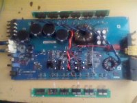
I've never seen one of these. The MIC4420s sound like it's a Rockford design. Can you post a photo of the inside of the amp?
Definitely Rockford judging by the MEHSA strips.
Sorry about photo quality but all I have is a camera phone.
Also, I know that it is missing a large polyester film capacitor near the output inductor, that was missing after he took it to the repair shop.
Sorry about photo quality but all I have is a camera phone.
Also, I know that it is missing a large polyester film capacitor near the output inductor, that was missing after he took it to the repair shop.
Attachments
Last edited:
Find the terminal of the output inductor that's NOT connected to the positive speaker terminal. Connect that terminal of the inductor to the negative speaker terminal with a jumper wire. Does that give you a cleaner signal on the gates of the FET?
I'm a little confused, I've got the two leads of the inductor that are connected to the output fets and I have the BLUE OUT + and BLK GND on the other side of the inductor. BLK GND is connected to the - speaker terminal already.
Which of the 4 leads of the inductor are you talking about connecting to - speaker?
Which of the 4 leads of the inductor are you talking about connecting to - speaker?
The inductor probably only has 2 terminals. The other two terminals are a loop around the core to prevent the core from moving. The terminal directly connected to the output FETs is the one you need to connect to ground (chassis and speaker ground are the same).
Yep, you are correct. One was a loop around that went nowhere. I didn't even look to see. 😱
I thought the inductor was connected to blue and black but it's only connected to blue, the other to the outputs. We all know what happens when we assume.
So with the outputs out of circuit I am basically grounding the would be output drains.
I thought the inductor was connected to blue and black but it's only connected to blue, the other to the outputs. We all know what happens when we assume.
So with the outputs out of circuit I am basically grounding the would be output drains.
Wow, the drive signal cleaned up nicely.
What exactly does tying the inductor to ground do to make the signal clean up? Something to do with the feedback loop?
What exactly does tying the inductor to ground do to make the signal clean up? Something to do with the feedback loop?
There is no stable reference point until you ground the input of the inductor. You can also short the speaker terminals but it's not as effective due to the reactance of the inductor. This can only be done when the outputs are out of the circuit.
Is it normal for the output section to get noticeably warmer than the power supply side in an amp like this? They don't get HOT but definitely warmer than the other side.
One of the noise filtering capacitors near the inductor is out of circuit. I figure all that would cause is noise but not sure if it would make the outputs warm up faster. It does produce audio, by the way.
One of the noise filtering capacitors near the inductor is out of circuit. I figure all that would cause is noise but not sure if it would make the outputs warm up faster. It does produce audio, by the way.
The best thing to do it to replace the cap to see if anything changes. It's normal for the outputs to operate at a slightly higher temps than the power supply FETs (in some amps) but, in general, they should not get hot quickly. If they get hot quickly after replacing the capacitor, then you can do further troubleshooting.
I'm assuming that the missing cap is in the output filter for the class D section of the amp.
I'm assuming that the missing cap is in the output filter for the class D section of the amp.
Yes, you can see in the previous photo that there is only one capacitor near the output inductor, it's 4.7uF 250V +-5%, there is also an empty space where there are cut leads in the solder joints.
If the cap was cut out because it was visually defective then maybe they both are.
If the cap was cut out because it was visually defective then maybe they both are.
Perry.I really enjoy reading your post,You are quickly becoming a legand to the Car Amp repair audiance.
Keep up the good work.
Keep up the good work.
That is nothing like the older strike 1K I have, it has large bobbin wound inductors on the output. The ones that like to break off the board. Mine are the blue sink with silver cover down the middle.
I haven't messed with this amp in a while mainly because I don't have power plugs for it but in either case, you were correct. After installing 2 new capacitors in the D class filter the outputs stay cool.
One question though, I ordered 4.7uF 250v caps and they are somewhat smaller than the originals. Should I be worried about their power handling capabilities even though they are both marked 250v?
Also, jol50, I have read in some RF forums about those just falling off the board, I will apply some silicone fixative to these so it doesn't happen again.
If the capacitor is a film/Mylar capacitor, it should be OK. The 10uF caps I buy from Digi-key are generally smaller than the originals they replace but I haven't had any fail yet.
Being that I do not have the power plugs and I'm not really concerned about them, is there any recommendations as to how to remove power terminals and just hard wire some 8 awg directly?
I find it difficult to either remove existing solder or to heat it up enough for them to break free.
I find it difficult to either remove existing solder or to heat it up enough for them to break free.
- Status
- Not open for further replies.
- Home
- General Interest
- Car Audio
- Lightning Audio Storm S1.1000