Don´t realy know how much is a joke and reality..Only when someone is making a mistake if they are used for a rectifier. They cost more too, so I guess they must be better!

I have a bunch of Byv26 in a box
 ,should I use them,I know I can but,any improvement with them?
Hi Ryssen,
Many experimenters believe a more expensive part is better, only on the grounds that the part is more expensive. It seems to escape many people that you should match the part to the job at hand.
If it doesn't smoke, it sounds better! (joke)
I don't know. I haven't look the part up to see the specs. If it's a regular rectifier diode it will probably perform the same as the original parts.
-Chris
I'm sorry. I was joking.Don´t realy know how much is a joke and reality..
Many experimenters believe a more expensive part is better, only on the grounds that the part is more expensive. It seems to escape many people that you should match the part to the job at hand.
If it doesn't smoke, it sounds better! (joke)
Good question.I have a bunch of Byv26 in a box ,should I use them,I know I can but,any improvement with them?
I don't know. I haven't look the part up to see the specs. If it's a regular rectifier diode it will probably perform the same as the original parts.
-Chris
Hi Ryssen,
Electrically, they shouldn't cause any problems. Just watch for noise on the raw supplies if you want to compare them.
Mechanically the leads may be too large and force you to enlarge the holes in the board. Not wise, especially if the board is double sided as they normally have plated through holes.
-Chris
There is no choke directly after the regulators,but it seems to be one on every IC on the rest of the boards..Adding a choke and cap after these might be a good idea, and before. That reduces the importance of regulator performance at higher frequencies.
Is it a waste to use a choke and a C after the regulators then?..
C-L-C-L-C..... 🙄
Hi Ryssen,
In my view, getting rid of any noise is best done at the source or close to the source. Everything else becomes much easier after that is done.
-Chris
I would say that it would be a wasted effort. I'm just trying to keep an open mind about this.There is no choke directly after the regulators,but it seems to be one on every IC on the rest of the boards..
In my view, getting rid of any noise is best done at the source or close to the source. Everything else becomes much easier after that is done.
-Chris
Anyone know how much the current draw is from the supplylines,3,3v 5v 5v +9v -9v ?Or maybe I should find my 1 ohms resistor  and messauer it....
and messauer it....Hi Ryssen,
It's always better to simply measure it yourself. While you are doing that, hook up a 'scope and look at the noise current.
-Chris
It's always better to simply measure it yourself. While you are doing that, hook up a 'scope and look at the noise current.
-Chris
Sure,If you tell me how..While you are doing that, hook up a 'scope and look at the noise current.
I have a scope.
Hi Ryssen,
Use you oscilloscope across the resistor. Make sure you "float" * your circuit or the scope, or heavy currents may flow through your 'scope and damage it.
The only other way to do this (to the best of my knowledge) would be to use a differential 'scope probe. Expensive.
-Chris
* Float. To remove the reference to ground so that all parts of your circuit are not referenced in any way to any fixed voltage. THis can be done with an isolation transformer. Beware that you do not connect anything to inputs or outputs.
If i don´t use/have an isolation trafo,doest it work to disconnect the mains protection earth?* Float. To remove the reference to ground so that all parts of your circuit are not referenced in any way to any fixed voltage. THis can be done with an isolation transformer. Beware that you do not connect anything to inputs or outputs.
Hi Ryssen,
It might. Check with a voltmeter. If you measure 0 volts AC and DC, try measuring the resistance between grounds.
If you aren't comfortable, don't try it. I don't want you to make a mistake and damage anything.
-Chris
It might. Check with a voltmeter. If you measure 0 volts AC and DC, try measuring the resistance between grounds.
If you aren't comfortable, don't try it. I don't want you to make a mistake and damage anything.
-Chris
Hi ,
-Chris
The voltage drop across your resistor. Measure it with a DC instrument and you get DC current. Measure it with an AC instrument and you get the AC component. With DC coupling you could read both.Hmmm,but how to measure ripple voltage with scope?
-Chris
Measure it with an AC instrument and you get the AC component.
What about a measurement preamplifier like this:
Yes,but you mean the scope isn´t sensetive enough to measure the ripple without an preamp?
Hi Ryssen,
-Chris
That is entirely possible.Yes,but you mean the scope isn´t sensetive enough to measure the ripple without an preamp?
-Chris
Tried to buy a PCB on the site,but he says he is out of boards,and waiting for more interests before making new ones.It could take one year he says!!What about a measurement preamplifier like this:
http://www.tangentsoft.net/elec/lnmp/

Unless anyone know of a similar amp?With pcb...
So I hocked up my scope,most sensetive,5mv-AC, to the +9v analog regulator on the PSU.And It locked like this:
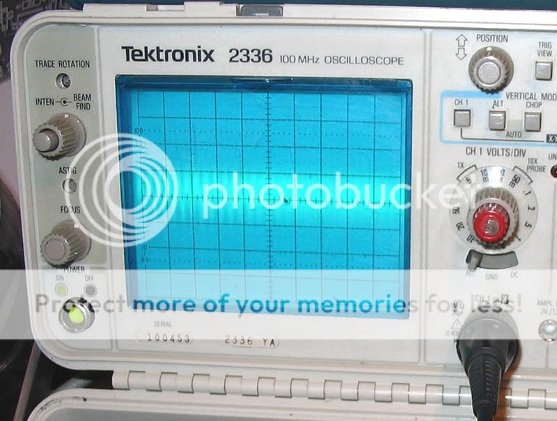
about 10-12mv I would say.10mv was the maximum input the measuring preamp at tangetsoft could take at input,it says at the site.

And at the analog pcb,opamp it locked like this:

The +5v supplys have a few mv lower.
If I want to measure ripple at the recitifier diods do I need to float the scope then?
Hi Ryssen,
One of those traces appeared to have some oscillation on it (last one before your schematic).
-Chris
One of those traces appeared to have some oscillation on it (last one before your schematic).
No, just AC couple it. Start at the higher range and reduce it once the input cap charges. Set your trigger source to "line".If I want to measure ripple at the recitifier diods do I need to float the scope then?
-Chris
This is the numbers i got:
+9volt opamps 100mA ~14mv
-9volt opamps 300mA ~14mv
+5volt analog 75mA ~15mv
+5volt digital 2ma ~10mv
The 2mA on the 5volt digital seems a little low,but I checked it meny times,and a cd was playing..
Now on to find some suitable regulators.
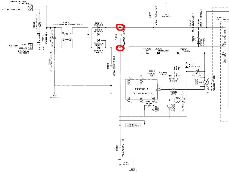
I got those readings before I...tried to measure the rectifier...The house went DARK..the earthbreaker switched of,tried it once more,the fuse in 3910 blew.Checking the diods one is shorted,so I got a reason to start modding then. Just hope the TOP245Y(PWM switch)did´nt blow...
+9volt opamps 100mA ~14mv
-9volt opamps 300mA ~14mv
+5volt analog 75mA ~15mv
+5volt digital 2ma ~10mv
The 2mA on the 5volt digital seems a little low,but I checked it meny times,and a cd was playing..
Now on to find some suitable regulators.
I got those readings before I...tried to measure the rectifier...The house went DARK..the earthbreaker switched of,tried it once more,the fuse in 3910 blew.Checking the diods one is shorted,so I got a reason to start modding then.
Just hope the TOP245Y(PWM switch)did´nt blow...- Status
- Not open for further replies.
- Home
- Source & Line
- Digital Source
- Light mod Denon 3910..