Tell me what you think about this.
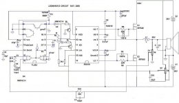
http://user.faktiskt.se/Tekko_Tubeamp/D-amp project/D-Amp alt gate drive.PNG
It eliminates the IR2010 that just keeps blowing up atleast, tho i dunno if this is better or worse.
http://user.faktiskt.se/Tekko_Tubeamp/D-amp project/D-Amp alt gate drive.PNG
It eliminates the IR2010 that just keeps blowing up atleast, tho i dunno if this is better or worse.
It say's forbidden. BTW, you ought to try emitter follower buffers after your driver, better switching and it may save your driver when the mosfets blow.
Is it not the case that you will still blow up the 2110?
VS will swing from +25V to -25V with respect to 0V, but VB is being supplied through the diode from +12V. This means that C2 will charge to 37V when VS goes to -25V, which will damage the chip when VS swings back to +25V.
VS will swing from +25V to -25V with respect to 0V, but VB is being supplied through the diode from +12V. This means that C2 will charge to 37V when VS goes to -25V, which will damage the chip when VS swings back to +25V.
Hello Tekko,
been closely following this thread and ledmania's.... 🙂
EVER considered driving the MOSFETS directly from the TL494??
is it possible??

hard time getting/ordering IR2010
RX5
been closely following this thread and ledmania's.... 🙂
EVER considered driving the MOSFETS directly from the TL494??
is it possible??
hard time getting/ordering IR2010
RX5
No you cannot drive them fets directly, but you can build a discrete gate driver, but then you must provide the delay necessary to prevent cross conduction in means of more IC´s on the board = byebye simplicity.
Oh Boy!! It's been two weeks that I didnt visit this forum and was surprised that I missed a lot of topic on this thread.
Yo Tekko, I'm so sorry for the pain and sorrow that you encounter in making this circuit but I cant help but to suggest only based on my analysis through your post I'm beginning to admire on your courage😉 .Well, that’s what a genuine hobbyist are for. No Pain!! No Gain!!!
But if you have some time to work with the circuit once again then please try my simple suggestions.
Step 1- Remove the L,C and the fb pot and leave it vacant for a while.
Step 2-Put the fb resistor 22k across pin3 and pin15 of tl494.
Step 3-put the power supply and check the voltage on pin 3, pin15 and 16(should be 2v)if not then tweak the pot.
Step 4-Sample the sound via headphone on pin 8 in series with a 10uf cap @ low volume please..you should hear a nice clean sound. Dont worry to that 100khz pulses, you wont hear it😀
Step 5- Sample the output pulses from the source and Drain of the power fets and you should get approx 50% duty(no music @ this time)... If not then tweak the pot.....50% duty will give you half of your Vcc. If the pulses are ok then….
step 6-sample the sound from the power fets with the headphone again with a 10uf cap (@ lo volume please) and notice the sound. If the sound is like what you heard on pin 8 of 494, then........
step 7- Put 1000uf25v from the vacant slot of the L and connect the subwoofer to it, then listen to the music @ low vol please. dont worry with the 100khz pulses. you wont hear it....
The inductive reactance of the sub is too high @ 100khz so it will suck little current..If you get a clean nice sound, then that’s it!, wait for that beloved toroid suggested by fredos to replace the 1000uf cap. This should work!!😉
Good luck
ledmania
Yo Tekko, I'm so sorry for the pain and sorrow that you encounter in making this circuit but I cant help but to suggest only based on my analysis through your post
I'm beginning to admire on your courage😉 .Well, that’s what a genuine hobbyist are for. No Pain!! No Gain!!! But if you have some time to work with the circuit once again then please try my simple suggestions.
Step 1- Remove the L,C and the fb pot and leave it vacant for a while.
Step 2-Put the fb resistor 22k across pin3 and pin15 of tl494.
Step 3-put the power supply and check the voltage on pin 3, pin15 and 16(should be 2v)if not then tweak the pot.
Step 4-Sample the sound via headphone on pin 8 in series with a 10uf cap @ low volume please..you should hear a nice clean sound. Dont worry to that 100khz pulses, you wont hear it😀
Step 5- Sample the output pulses from the source and Drain of the power fets and you should get approx 50% duty(no music @ this time)... If not then tweak the pot.....50% duty will give you half of your Vcc. If the pulses are ok then….
step 6-sample the sound from the power fets with the headphone again with a 10uf cap (@ lo volume please) and notice the sound. If the sound is like what you heard on pin 8 of 494, then........
step 7- Put 1000uf25v from the vacant slot of the L and connect the subwoofer to it, then listen to the music @ low vol please. dont worry with the 100khz pulses. you wont hear it....
The inductive reactance of the sub is too high @ 100khz so it will suck little current..If you get a clean nice sound, then that’s it!, wait for that beloved toroid suggested by fredos to replace the 1000uf cap. This should work!!😉
Good luck
ledmania
Do the IR2110 keep blowing because you don't know how to use them??
Yeah!! So you want to use another gate drive approach... How a lame solution 😀
Yeah!! So you want to use another gate drive approach... How a lame solution 😀
I know well how to use them.
I wil NEVER again try to use puter ps filter toroids for class d.
Two T106-2 toroids are ordered.
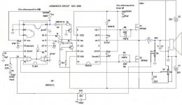
Ledmania, i actually encountered an error in your schematic, one of the inverters was on the wrong input on your later schemas, but on the right place on your first schema.
Just to let u know.
I´ll try your suggestions.
I wil NEVER again try to use puter ps filter toroids for class d.
Two T106-2 toroids are ordered.
Ledmania, i actually encountered an error in your schematic, one of the inverters was on the wrong input on your later schemas, but on the right place on your first schema.
Just to let u know.
I´ll try your suggestions.

New coil is in and its a huge step, it works way better with bass now, but still the same story with single woofers 🙁
This meansd the it wasent because of the coil after all, it is something else.
This meansd the it wasent because of the coil after all, it is something else.
Ledmania. I have now tried the headphone thing on the TL494 as you said with a 32ohm speaker, works fine.
Ledmania, Y0 heads up. The amp is finally working as it should😀 😀
The feedback was the problem all along. As it is now the fb loop is pin3 and pin15 on the 494.
It pounds loud bass and performs well fullrange.
The feedback was the problem all along. As it is now the fb loop is pin3 and pin15 on the 494.
It pounds loud bass and performs well fullrange.
Tekko said:Ledmania, Y0 heads up. The amp is finally working as it should😀 😀
The feedback was the problem all along. As it is now the fb loop is pin3 and pin15 on the 494.
It pounds loud bass and performs well fullrange.
Well, congratulations!! 😉
If you are happy, then i'm happy too!😀
But I'm going to look for another possible fb to be added @ the output of the fet itself because that is the primary goal of that circuit. Oh well!
Now your smilin!!😉The problem turned out to be phase. The fb should goto the input on the erroramp where the 2Vref goes, otherwise it is a class d oscillator. Or you need a phase something network on the fb.
Right now i have the fb between pin 3 and 15 on the 494.
Btw join us on the irc channel.
Heres some pics of the amp: http://user.faktiskt.se/Tekko_Tubea...e sided/plugged in/work done/finally working/
Right now i have the fb between pin 3 and 15 on the 494.
Btw join us on the irc channel.
Heres some pics of the amp: http://user.faktiskt.se/Tekko_Tubea...e sided/plugged in/work done/finally working/
Tekko said:The problem turned out to be phase. The fb should goto the input on the erroramp where the 2Vref goes, otherwise it is a class d oscillator. Or you need a phase something network on the fb.
Right now i have the fb between pin 3 and 15 on the 494.
Btw join us on the irc channel.
Heres some pics of the amp: http://user.faktiskt.se/Tekko_Tubea...e sided/plugged in/work done/finally working/
Tekko, I'd been trying many times to open your file even inside my own thread about two weeks ago but it say's "Forbiden"
Please try to use "Image shack hosting" like the way I use to show my schema. You see? Even class d for sure encounter the same fate like me. LOL! LOL! LOL!
Go ahead there now to image shack and practice posting your pics

Primoz said:delete "finally%20working/" in address line in your browser, and link will work
LOL!😀 It works!! Thanks Primoz!!
WOW! I'm very envy with you Tekko😀
I wanna go home and try it toooooo!!!LOL! LOL!LOL!
- Status
- Not open for further replies.
- Home
- Amplifiers
- Class D
- level shifters and mosfet drivers