Well the diode has a Vf that is within a small window and all the rest of the voltage is then "dropped" across the resistor, right? 🙂Apparently many don't see that but I am glad I am not the only one that does see it. Since they were intended for DC use it seems the simplest and most optimal way of dealing with them.
* It is a current limiting resistor. Dropping resistors limit voltage AFAIK.
Still it is a current limiting resistor as current is the parameter that must be limited.
R led = (U bat - Uf led)/I led
R led = (U bat - Uf led)/I led
Last edited:
No, maybe it is good to follow standard lingo. Main subject/part is the LED that needs the current limited, not voltage.
Diode, 22 kOhm series resistor (for 24V AC), 1 ... 10 µF cap, second 22 ... 100 Ohm series resistor + LED.
High part count for an indicator light.
I hate this thread already.
Attachments
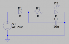
No hate just love. You should add the main current limiting resistor and the antiparallel diode I forgot to mention based on the info Elvee provided (I think). It was the leakage current of D1 that made the LED blow up. This is prevented/solved by adding the antiparallel diode. R1 was meant to overcome the issues that come with the LEDs parameters in combination with a parallel cap as mentioned by Elvee.
Last edited:
I use a blue LED as a power indicator on my tube amp.
It's fed from the 6.3v filament winding, through a 1N4007 diode, then a 4.7K resistor, to the LED.
It's lasted since 2006 withoout a problem.
I think a 4.7K with 24V is a bit too low.
It's fed from the 6.3v filament winding, through a 1N4007 diode, then a 4.7K resistor, to the LED.
It's lasted since 2006 withoout a problem.
I think a 4.7K with 24V is a bit too low.
Blue LEDS of today are different. They lighten your whole living room at 1 mA. Well, almost. We learned that they are also quite sensitive to reverse voltages.
One could use a diode-cap-voltage regulator-cap-series resistor-LED to overcome all the blue LED issues 🙂 The anti-KISS approach.
One could use a diode-cap-voltage regulator-cap-series resistor-LED to overcome all the blue LED issues 🙂 The anti-KISS approach.
Last edited:
I would use a 'normal' LED, this is complicated, and failure prone.
Use a bridge rectifier, drop / current limiting resistor, smoothing cap, 3V9 zener (if needed), as a possible supply. Pure controlled DC.
Alternately, 22V SMD LEDs are available, used in lamps, bulk packing.
They will not blow up so easily.
Use a bridge rectifier, drop / current limiting resistor, smoothing cap, 3V9 zener (if needed), as a possible supply. Pure controlled DC.
Alternately, 22V SMD LEDs are available, used in lamps, bulk packing.
They will not blow up so easily.


Nice circuits, especially the second one with standby indication! Almost more complex than the device they are built in 🙂 Hey if it floats your (blue) boat....
Some hesitance to bring higher voltages to a front panel LED though. In the past a few extra windings on the toroid with normal insulated wire to the standard green LED and just a series resistor also worked. Safe, simple, cheap and reliable.
Some hesitance to bring higher voltages to a front panel LED though. In the past a few extra windings on the toroid with normal insulated wire to the standard green LED and just a series resistor also worked. Safe, simple, cheap and reliable.
Last edited:

You're right!
But I wanted an indicator each for on and off state. Wouldn't work with voltage from the switched transformer.
The LEDs also aren't put directly in the front panel. I would see isolation issues with them looking through a metal panel.
The panel is either of transparent Plexi and the LED is shining through it (Like here).
Or there is a kind of light guide from Plexi which reaches trough the panel.
Why easy when it can be complicated 😀
Yes that is the spirit. I just disassembled a device that can only be disassembled destructively (nice) and that one has a microcontroller for standby, power on and the LEDs blinking.
Wow! That link directed me straight to hardcore electro-porno. Never do that again.
Wow! That link directed me straight to hardcore electro-porno. Never do that again.
As I've always mentioned, I like to keep things simple, and thus reliable.
One amp I'm working on uses a blue/red LED for standby/on, DC powered from a tiny standby transformer which also kicks in a speaker delay relay.
The 3 position source selector also powers 3 LED's - blue for phono, red for CD, and green for aux.
One amp I'm working on uses a blue/red LED for standby/on, DC powered from a tiny standby transformer which also kicks in a speaker delay relay.
The 3 position source selector also powers 3 LED's - blue for phono, red for CD, and green for aux.
Wiseoldtech again... with even 2 blue LEDs to laser the eyes 😀 I take it is blue for power on and red for standby?! Otherwise many would be switching stuff off instead of on.
That sounds like a modern bicycle light, one of those battery-powered models that are not permanently attached to the bike. I frequently find damaged ones on the pavement or the street and then re-use the LEDs.Yes that is the spirit. I just disassembled a device that can only be disassembled destructively (nice) and that one has a microcontroller for standby, power on and the LEDs blinking.
Nein, it is a dual output linear PSU from a leftover lot by a certain audio brand. All new in box saved from recycling.
???That link directed me straight to hardcore electro-porno
Never heard of that.
Googling the term leads me to some pages, which have nothing to do with the issue under the link. 😆
Yes Jean-Paul, blue for ON.... red for Standby.Wiseoldtech again... with even 2 blue LEDs to laser the eyes 😀 I take it is blue for power on and red for standby?! Otherwise many would be switching stuff off instead of on.
CORRECTION: Both are OFF when unit is OFF.
The red illuminates at power ON... then switches to BLUE when the delayed speaker relay kicks in.
And they both are dimmed to a comfortable glow and show through a single frosted lens, as are the selector LED's
I dislike bright LED indicators.
Last edited:
- Home
- Amplifiers
- Power Supplies
- LED keeps blowing on AC supply