Hum pot on heaters
It works by making the AC applied down each heater wire "equal and opposite" , thereby causing (near) cancellation.
You just adjust it for minumum hum.
It works by making the AC applied down each heater wire "equal and opposite" , thereby causing (near) cancellation.
You just adjust it for minumum hum.
SIDE EFFECT.
Hi,
Another advantage is that the cathode is likely more evenly heated avoiding hot and cold spots.
This should provide better emission over the cathodes' surface.
It can be applied on DC heaters as well.
Ciao,😉
Hi,
Another advantage is that the cathode is likely more evenly heated avoiding hot and cold spots.
This should provide better emission over the cathodes' surface.
It can be applied on DC heaters as well.
Ciao,😉
signal path and operating point
Hello,
Just a couple of quick, basic questions, please.
Do you all have favorite op points for a given tube (say 6bq5) and can you tell a difference in the op points? If so, can you describe the sonic differences as relates to "typical operating" conditions usually given in data sheets. That is higher voltage, lower current, higher bias, for example.
Also, which components do you consider "in the signal path"?
Aspiring diyer,
Rick
Re: signal path and operating point
All of them?🙄
fragman56 said:Also, which components do you consider "in the signal path"?
All of them?🙄
ALL OF THEM?
Hi,
Well,I think it is wise to distinguish between components that are in the direct signal path and the rest of the circuit.
While all of them are important and need to be chosen wisely the quality of those components directly in the signal path would need the most attention qualitywise in the first place.
At the end of the day it is very hard to say that this or that part of the circuit can be neglected,this is just not the case.
Depending on the type of circuit and its' typical behaviour and the load it is going to see and the task it has to perform, it will require more or less attention...
As you can see you just can't generalise on a question like this.
The first part of your question,load lines,class of operation etc fall into the same category,all this attention to detail and understanding what is to be expected of the circuit will determine your compromises.
Obviously you can't turn a badly thought out circuit into a little gem just by using top quality components...it would make it all the more apparent that money has been wasted.
Hope it helps,😉
Hi,
Also, which components do you consider "in the signal path"?
Well,I think it is wise to distinguish between components that are in the direct signal path and the rest of the circuit.
While all of them are important and need to be chosen wisely the quality of those components directly in the signal path would need the most attention qualitywise in the first place.
At the end of the day it is very hard to say that this or that part of the circuit can be neglected,this is just not the case.
Depending on the type of circuit and its' typical behaviour and the load it is going to see and the task it has to perform, it will require more or less attention...
As you can see you just can't generalise on a question like this.
The first part of your question,load lines,class of operation etc fall into the same category,all this attention to detail and understanding what is to be expected of the circuit will determine your compromises.
Obviously you can't turn a badly thought out circuit into a little gem just by using top quality components...it would make it all the more apparent that money has been wasted.
Hope it helps,😉
Re: signal path and operating point
Rick - the operating point you choose largely depends on the supply you want to use, and the output transformers you have available. It's all intertwined though... if you raise the primary impedence, the distortion, output, response all change. If you raise the plate voltage, the optimal load changes. This goes on and on.
There is no easy answer to that one either.
fragman56 said:Do you all have favorite op points for a given tube (say 6bq5) and can you tell a difference in the op points? If so, can you describe the sonic differences as relates to "typical operating" conditions usually given in data sheets.
Rick - the operating point you choose largely depends on the supply you want to use, and the output transformers you have available. It's all intertwined though... if you raise the primary impedence, the distortion, output, response all change. If you raise the plate voltage, the optimal load changes. This goes on and on.
There is no easy answer to that one either.
Re: signal path and operating point
For the 6BQ5, I like Va = 250V, Ia = 35mA, Vg = -9.5V, Rk = 270R Rload = 3k5 (SE) or 7k (PP). If you don't need all the voltage swing in an application, up the current to 40mA. The 6BQ5 / EL84 is a very sweet (ie good) tube.
If I'm new to a tube, I use the factory recommended op points. In many instances later experimantation has proven (to me) that the factory op points are usually very good. The WE, STC and Genalex datasheets have proven to be excellent. My advice would be to build it using the factory suggested points, and then try changing some things around a bit to move the points, and see how it sounds to you. No matter what any of us say, you'll learn a lot more by listening for yourself, and the costs are very small esp compared to the benefit in the learning.fragman56 said:Do you all have favorite op points for a given tube (say 6bq5) and can you tell a difference in the op points? If so, can you describe the sonic differences as relates to "typical operating" conditions usually given in data sheets. That is higher voltage, lower current, higher bias, for example.
For the 6BQ5, I like Va = 250V, Ia = 35mA, Vg = -9.5V, Rk = 270R Rload = 3k5 (SE) or 7k (PP). If you don't need all the voltage swing in an application, up the current to 40mA. The 6BQ5 / EL84 is a very sweet (ie good) tube.
All of them (including the power supply), but they're not neccessarily of equal importance, nor will they all have the same sonic effect.Also, which components do you consider "in the signal path"?
SO FAR SO GOOD.
Hi,
Yep,seems you got yourself something cookin'.
Keep it it coming,we're here to help.😉
Hi,
Yep,seems you got yourself something cookin'.
Keep it it coming,we're here to help.😉
scheme of amp revised
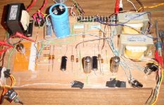
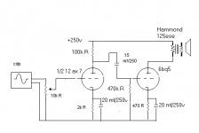
here is the schematic of the amp in picture
I measured about 1v into the 12ax7, about 5v out of 12ax7 and about 30v out of the 6bq5.
Do those values seem about right?
Also, I have tried a 100k pot at input and it did not sound good so I went back to the 10 turn pot (10k).
I have been listening to this contraption for about 1 month at different op points, pots, PSU configs...my tin ears like it.
Suggestions for learning/improvements? Switch 12ax7 for other tubes (5755, 12au7, ...)
Aspiring Diyer,
Rick
Attachments

And to continue...
So could I simply add another stage, say a 300b with Hammond 1627's and a separate power transformer assuming correct biasing and coupling?
That is, use the el 84 to drive the 300b with basically same setup? Of course, this is the breadboard version...will build nice version with quality components and chassis later if it all works.
I guess I should expect about 8 watts with the 300b in se mode?
thanks for your comments,
Rick
quick question
I just measured the output of the 12ax7 driver to the el 84 se output tube and got a lot of audible distortion at about 10 v on the o-scope. Is this to be expected?
Operating point for driver stage is 160 v and .75 ma. Using about 250v on the plate. I was expecting to get about 70 volt pk to pk (with cdp) with this driver and very little distortion. Can't get anywhere near this without poor sound.
Your thoughts and comments appreciated.
Rick
Rick, 70 volts peak-peak is going to overload any 6BQ5.
The output tube should be biased at what, minus 14 or 15 volts?
So, the biggest swing you can deliver to those grids is 30 volts, pk-pk.
Make sense?
So, your output tubes are slightly underbiased if you get clipping at 10 volts. Increase the value of the cathode resistor.
The output tube should be biased at what, minus 14 or 15 volts?
So, the biggest swing you can deliver to those grids is 30 volts, pk-pk.
Make sense?
So, your output tubes are slightly underbiased if you get clipping at 10 volts. Increase the value of the cathode resistor.
Oh, I see!
Thanks for the simple explanation (I have ordered the RDH but not received it yet).
You have explained it well and simply and it makes perfect sense now. Thank you.
Rick
Thanks for the simple explanation (I have ordered the RDH but not received it yet).
You have explained it well and simply and it makes perfect sense now. Thank you.
Rick
Joel's driver tube
I replaced the 12ax7 driver tube with a 5755 driver in my breadboarded se el84 amp and found something very interesting to me: an audible hum.
Previously with the 12ax7, very little hum was present especially using a 100 ohm hum pot. Also, when my hand is placed near the driver tube, the frequency varies!!
I am using the same configuration--just changed the driver. Is this tube more sensitive to rf signals? Or, perhaps, microphony?
Any thoughts?
Rick
Rick, I had the same thing happen to me.
I bought a lot of ten 5755's for a buck a piece, and the first one I used produced a hum that changed when I moved my hand near the tube! I replaced that tube with another from the same lot and.... hum was gone. That tube has been in the amp for two years now and has never had a problem.
I can't explain it. 😕
But for $1 or so each, you really can't complain.
This DIY-thing drives me nuts!!!
Joel,
Thank you so much for the response!!
I bought 10 of them also and will change the rogue out to a good one tonight.
I like the 5755 driver and will construct a permanent 2 watt se amp. What do the 5755 series grid resistors do?
Also, I am using a 10k vol pot in lieu of a 100k--ok or should I change to 100k?
Just got my 1482 page RDH--mercy! Gonna be a long time reading.
Does anyone else have trouble sleeping when your project does not work properly??
BTW, ever tried a choke and capacitor coupled output system instead of a output transformer?
Thanks,
Rick
Re: This DIY-thing drives me nuts!!!
I would. Unless you enjoy tossing away signal voltage. In fact, I would use a 250K.
Yes. I also tend to not eat much.
I haven't. But it looks cool. That's really old school.
fragman56 said:Also, I am using a 10k vol pot in lieu of a 100k--ok or should I change to 100k?
I would. Unless you enjoy tossing away signal voltage. In fact, I would use a 250K.
Does anyone else have trouble sleeping when your project does not work properly??
Yes. I also tend to not eat much.
BTW, ever tried a choke and capacitor coupled output system instead of a output transformer?
I haven't. But it looks cool. That's really old school.
- Status
- Not open for further replies.
- Home
- Amplifiers
- Tubes / Valves
- learning, building and testing tube amp